Home · Book Reports · 2017 · Digital Design - An Embedded Systems Approach Using VHDL

- Author :: Peter J. Ashenden
- Publication Year :: 2007
- Read Date :: 2017-12-27
- Source :: (2007)_Digital_Design_(VHDL) An_Embedded_Systems_Approach_Using_VHDL.pdf
designates my notes. / designates important.
Thoughts
After finishing the Bruce Land/Cornell FPGA/Verilog course, ECE5760 (2011), I found out that there is a new version available for 2017. I haven’t gone through the 2017 version yet, but assuming they are similar to the 2011 version, they will be worthwhile.
I did work my way through the first 30 or so videos of the VHDL tutorial from LBE Books while reading this. These cover a few of the topics skipped by this book, particularly Karnaugh Maps and Quine-McClusky minimization. As with anything, you will learn more by doing than reading. These are short and sweet and great practice fodder to try to implement yourself without looking back at the video.
This book is a good compromise between low level gate logic and higher level abstraction. Definitely not the first book you want to pick up on electrical engineering or VHDL, but if you have a solid understanding of EE and a software foundation to approach the VHDL component for, it is a worthwhile book.
- The book’s own summary pretty much covers it:
We have now completed our foundational study of digital system design. We started with the basic elements of digital logic, gates and flip-flops, and showed how they can be used in circuits that meet given functional requirements. Given the complexity of requirements for most modern systems, we appealed to the principle of abstraction as a means of managing complexity. In particular, we use hierarchical composition to build blocks from the primitive elements, and systems from those blocks. By this means, we were able to reach the level of complete embedded systems, comprising processors, memories, I/O controllers, and accelerators, without becoming overwhelmed by the detailed interactions of the millions of transistors involved. Throughout our study, we also paid attention to the design methodology real-world effects that arise in digital circuits and the constraints that they imply. We showed how a disciplined design methodology helps us meet functional requirements while satisfying constraints. The study of digital systems in this book serves as a foundation for further studies in several areas.
Other references that may be of interest:
-
2008 Designers Guide to VHDL
-
A Guide to Debouncing, Jack G. Ganssle, The Ganssle Group, 2004, www.ganssle.com/debouncing.pdf. Presents empirical data on switch bounce behavior, and describes hardware and software approaches to debouncing.
-
OpenCores, www.opencores.org. From the website’s FAQ, “OpenCores is a loose collection of people who are interested in developing hardware, with a similar ethos to the free software movement.” The website hosts a repository of freely reusable core designs, many of which are compatible with the Wishbone bus.
-
Computers as Components: Principles of Embedded Computing System Design, Wayne Wolf, Morgan Kaufmann Publishers, 2005. Includes a discussion of accelerators in the context of embedded hardware and software design, with a video-processing accelerator as a case study.
Table of Contents
- CHAPTER 1: Introduction and Methodology
- CHAPTER 2: Combinational Basics
- CHAPTER 3: Numeric Basics
- CHAPTER 4: Sequential Basics
- CHAPTER 5: Memories
- CHAPTER 6: Implementation Fabrics
- CHAPTER 7: Processor Basics
- CHAPTER 8: I/O Interfacing
- CHAPTER 9: Accelerators
- CHAPTER 10: Design Methodology
· CHAPTER 1: Introduction and Methodology
page 21:
- Designing electronic circuits using CAD tools is also called electronic design automation (EDA).
page 28:
page 29:
page 32:
page 34:
-
Static and capacitive loading limits the fanout of a driver, that is, the number of inputs that can be connected to the output.
-
Propagation delay depends on delay within components, capacitive loading and wire delays. Flip-flops have setup and hold time windows and clock-to-output delays.
-
A behavioral model describes the function performed by a circuit. A structural model describes the circuit as an interconnection of components.
· CHAPTER 2: Combinational Basics
page 41:
- For a Boolean expression with n distinct variables, there are 2^n combinations, so we need 2^n rows.
page 48:
page 49:
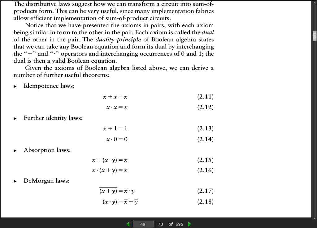
- The duality principle of Boolean algebra states that we can take any Boolean equation and form its dual by interchanging the “+” and “*” (dot) operators and interchanging occurrences of 0 and 1
page 52:
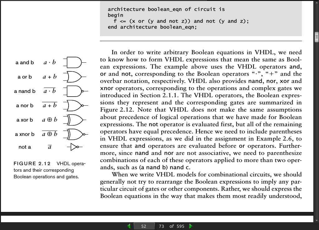
- When we write VHDL models for combinational circuits, we should generally not try to rearrange the Boolean expressions to imply any particular circuit of gates or other components. Rather, we should express the Boolean equations in the way that makes them most readily understood,
page 56:
-
an n-bit code has 2 possible code words, so an n-bit code can represent information with up to 2^n values. Conversely, if we need to represent information with N values, we need at least ⎡log_2 N⎤ bits in our code. (The notation ⎡x⎤ is called the ceiling of x, and denotes the smallest integer that is greater than or equal to x.)
-
While it might make sense in some cases to use the shortest code, in other cases a longer code is better. A particular case of a non–minimal- length code is a one-hot code, in which the code length is the number of values to be encoded. Each code word has exactly one 1 bit with the remaining bits 0. The advantage of a one-hot code becomes clear when we want to test whether the encoded multibit signal represents a given value; we just test the single-bit signal corresponding to the 1 bit in the code word for that value.
page 61:
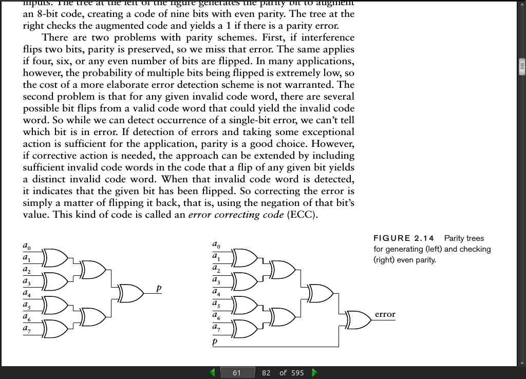
- use an exclusive-OR gate to generate the parity bit to augment a 2-bit code. We can extend this to augment a 3-bit code by taking the exclusive OR of the parity of two bits with the third bit. In general, for a code of any length, we can just take the exclusive OR of all of the bits. Since the exclusive-OR function is commutative and associative, the order in which we apply the exclusive OR to the bits of the code doesn’t matter. A common approach is to use a parity tree, as shown in Figure 2.14, since it keeps the overall propagation delay small and avoids using gates with large numbers of inputs. The tree at the left of the figure generates the parity bit to augment an 8-bit code, creating a code of nine bits with even parity. The tree at the right checks the augmented code and yields a 1 if there is a parity error.
page 72:
- One reason for using active-low logic is that some kinds of digital circuits are able to sink more current when driving an output low than they can source when driving the output high.
page 79:
· CHAPTER 3: Numeric Basics
page 91:

- VHDL has a standard package of numeric operations that are useful for design and synthesis of arithmetic circuits, so it is best to use the types provided by that package. The package is called numeric_std, and it resides in the standard library of packages, ieee.
ieee.numeric_std.all;
page 94:
- The 4-bit patterns corresponding to the hexadecimal digits are:
0: 0000
1: 0001
2: 0010
3: 0011
4: 0100
5: 0101
6: 0110
7: 0111
8: 1000
9: 1001
A: 1010
B: 1011
C: 1100
D: 1101
E: 1110
F: 1111
page 97:
- An alternate way of expressing both zero extension and truncation of unsigned values is to use the resize operation defined in the numeric_std package. For example, the above assignments could be written as
y <= resize(x, 8);
and
x <= resize(y, 4);
- Writing the operation in this way makes our intention clearer. However, the operation is only available for the types defined in the numeric_std package. Should we need to extend or truncate std_logic_vector values in order to implement some form of code conversion, we would have to use the concatenation operator or slicing.
page 106:
- The notation z’length means “the length of the vector z.”
page 107:
page 113:
-
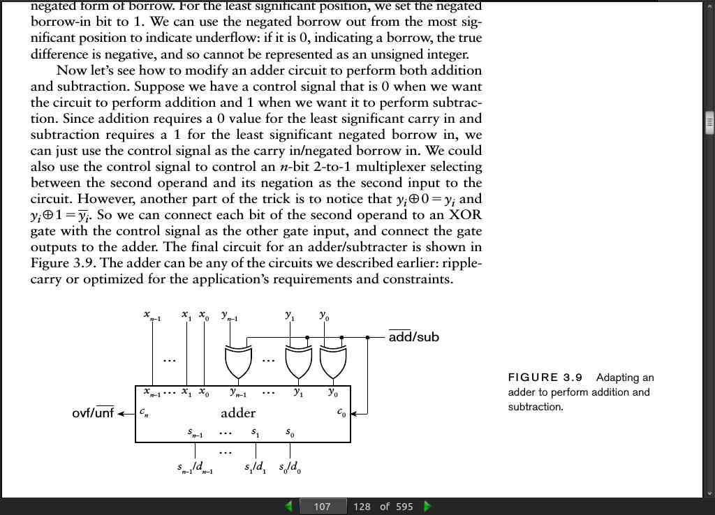
When we introduced the XNOR gate in Section 2.1.1, we mentioned that it is also called an equivalence gate, since its output is 1 only when its two inputs are the same. Thus, we can test for equality of two unsigned binary numbers using the circuit of Figure 3.11, called an equality comparator. In practice, an AND gate with many inputs is not workable, so we would modify this circuit to better suit the chosen implementation fabric. Better yet, we would express the comparison in a VHDL model and let the synthesis tool choose the most appropriate circuit from its library of cells.
-
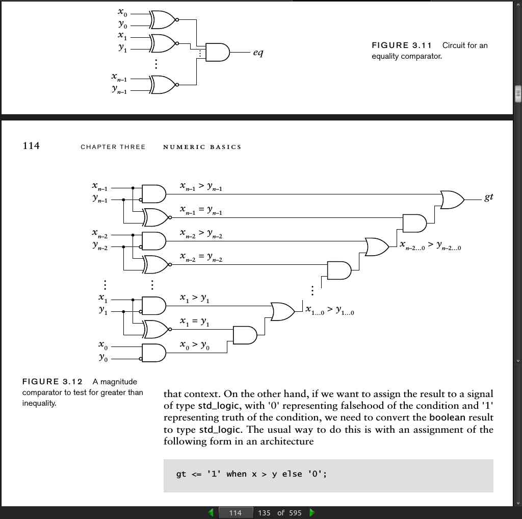
To test whether a number x is greater than another number y, we can start by comparing the most significant bits, x_n-1 and y_n-1. If x_n-1 > y_n-1, we know immediately that x > y. Similarly, if x_n-1 < y_n-1, we know immediately that x<y. In both cases, the final result is completely determined by comparing just the most significant bits. If x_n-1 = y_n-1, the result depends on the remaining bits, and is true if and only if x_n-2…0 > y_n-2…0. We can now apply the same argument recursively, examining the next pair of bits, and, if they are equal, continuing to less significant bits. Note that x_i > y_i is only true for x_i = 1 and y_i = 0, that is, if x_i AND ~y_i is true. These considerations lead to the circuit of Figure 3.12, called a magnitude comparator.
page 114:
page 116:
shift_left(s, 2)
shift_right(s,2)
page 117:
page 123:
- Example 3.14
What values are represented by the 8-bit 2s-complement numbers 00110101 and
10110101?

Solution
The first number is:
1 x 2^5 + 1 x 2^4 + 1 x 2^2 + 1 x 2^0 = 32 + 16 + 4 + 1 = 53
The second number is;
-1 x 2^7 + 1 x 2^5 + 1 x 2^4 + 1 x 2^2 + 1 x 2^0 = -128 + 32 + 16 + 4 + 1 = -75
page 124:
- We would use a mixture of signed and integer signals in a model if we need to access the bits of the 2s-complement encoding of some values but want other values to be in abstract form. For example
signal n1, n2 : integer                 -- implies an
                range –2**7 to 2**7–1;  -- 8-bit range
signal x, y : signed( 7 downto 0);
signal z : signed(11 downto 0);
signal z_sign : std_logic;
n1 <= to_integer(x);
n2 <= n1 + to_integer(y);
z <= to_signed(n2, z'length);
z_sign <= z(z'left);
- The operation to_integer, applied to a signed value, converts from a 2s-complement vector value to an abstract numeric value. The conversion 3.2 Signed Integers to_signed works in the reverse direction, from an abstract integer to a 2s-complement vector. The notation z’left in the last assignment means “the left-most index of the vector z.”
page 126:
-
For negative numbers, the sign bit is 1. We can extend an n-bit negative number to m bits by appending leading 1 bits.
-
In summary, for a 2s-complement signed integer, extending to a greater length involves replicating the sign bit to the left. This is called sign extension, and preserves the numeric value, be it positive or negative.
page 127:
-
We can truncate by discarding the left-most bits, provided all of the discarded bits and the resulting sign bit are the same as the original sign bit.
-
We can express sign extension or truncation of a signed value in a VHDL model by using the resize operation.
signal x : signed( 7 downto 0);
signal y : signed(15 downto 0);

we can write the following assignment statement in an architecture to sign
extend the value of x and assign it to y:

y <= resize(x, y'length);

Similarly, we can write the following assignment to truncate the value of
y and assign it to x:

x <= resize(y, x'length);
page 128:
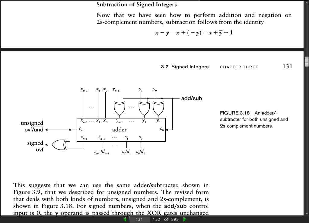
- Since we can represent both positive and negative numbers using 2s-complement encoding, it makes sense to consider negating a number. The steps needed to perform negation of a number x are first to complement each bit of x (that is, change each 0 to 1 and each 1 to 0), and then to add 1.
page 130:
signal v1, v2 : signed(11 downto 0);
signal sum : signed(12 downto 0);

we can add the two 12-bit values and get a 13-bit result using the assignment

sum <= resize(v1, sum'length) + resize(v2, sum'length);
signal x, y, z : signed(7 downto 0);
signal ovf : std_logic;

we can write the following assignments to derive the required sum and
overflow condition bit:

z <= x + y;
ovf <= ( not x(7) and not y(7) and z(7) ) or
       ( x(7) and y(7) and not z(7) );
page 131:
signal v1, v2 : signed(11 downto 0);
signal diff : signed(12 downto 0);

we can calculate the 13-bit difference between the two 12-bit values using
the assignment

diff <= resize(v1, diff'length) – resize(v2, diff'length);
signal x, y, z : signed(7 downto 0);
signal ovf : std_logic;

we can write the following assignments to derive the required difference
and overflow condition bit:

z <= x – y;
ovf <= ( not x(7) and y(7) and z(7) ) or
       ( x(7) and not y(7) and not z(7) );
page 135:
Example 3.18
What number is represented by the fixed-point binary number 01100010, assuming
the binary point is four places from the right?

solution
The number is 0110.00102
= 0x2^3 + 1x2^2 + 1x2^1 + 0x2^0 + 0x2^-1 + 0x2^-2 + 1x2^-3 + 0x2^-4
= 0 + 4 + 2 + 0 + 0 + 0 + 1/8 + 0 = 6.125_10
page 136:
Example 3.19
 What number is represented by the signed fixed-point
binary number 111101, assuming the binary point is four places from the right?

solution
The number is 11.11012
= -1x2^1 + 1x2^0 + 1x2^-1 + 1x2^-2 + 0x2^-3 + 1x2^-4
= -2 + 1 + 1/2 + 1/4 + 0 + 1/16 = -0.1875_10
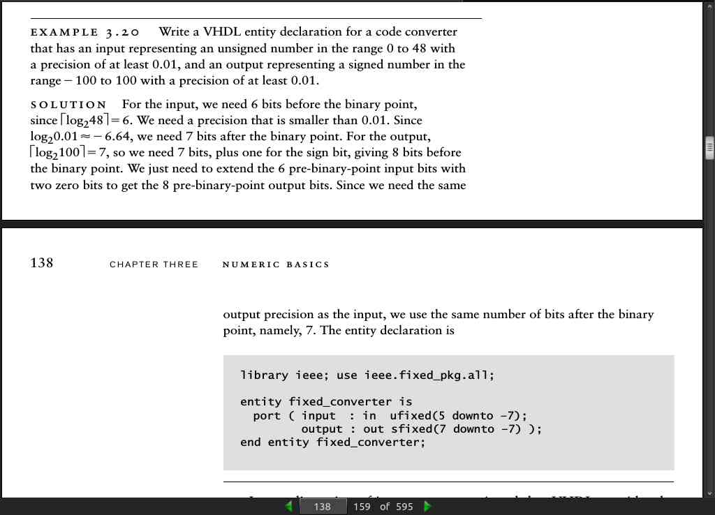
- We can represent fixed-point numbers in VHDL using the package fixed_pkg defined in library ieee. The package defines two types: ufixed for unsigned fixed-point numbers and sfixed for signed 2s-complement fixed-point numbers. Both types are vectors of std_logic elements, but are distinct types from each other and from the std_logic_vector type. For both types, we specify the left and right index bounds, indicating the power of two for the weights of the most significant and least significant bits, respectively. The binary point is assumed to be between indices 0 and Ϫ1, whether those indices actually occur in a given vector or not.
page 138:
page 142:
page 145:
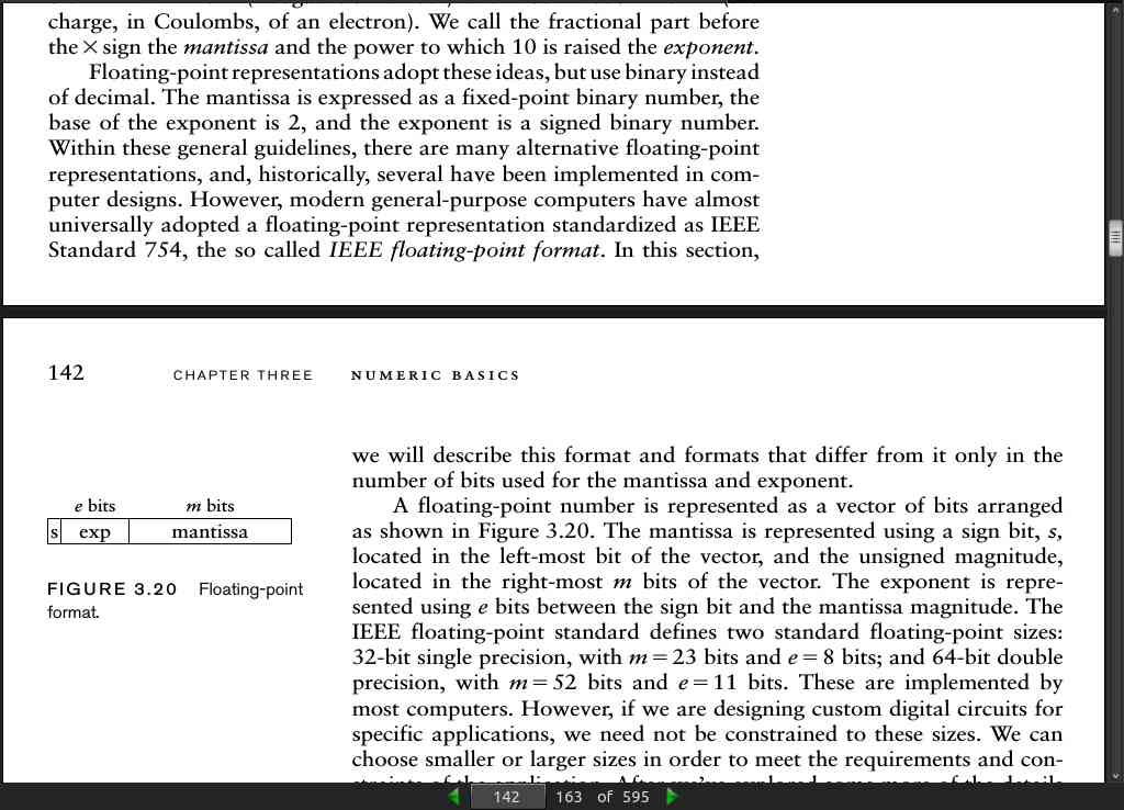
- To represent a floating-point number with e exponent bits and m mantissa magnitude bits, we declare a signal of type float with e as the left index bound and Ϫm as the right index bound. The sign bit is then the element at index e, the exponent is the slice from e Ϫ 1 down to 0, and the mantissa magnitude (without the hidden bit) is the slice from Ϫ1 down to Ϫm. For example, a floating-point signal with 5 exponent bits and 10 mantissa-magnitude bits would be declared as
signal fp_num : float(5 downto –10);
- The sign bit would then be fp_num(5), the exponent fp_num4(4 downto 0), and the mantissa magnitude fp_num(–1 downto –10).
page 146:
- While we can use type real as an abstraction for floating-point and fixed-point numbers, we don’t have the fine control over the range and precision afforded by types ufixed, sfixed and float. Nonetheless, using type real can be valuable for exploration of numerical algorithms in the early design stages, especially since simulators will perform computations on real values much faster than on ufixed, sfixed or float values.
page 148:
- Binary-coded integers are multiplied by a power of two by a logical shift left. Unsigned integers are divided by a power of 2 by a logical shift right. 2s-complement signed integers are divided by a power of 2 by an arithmetic shift right.
page 159:
· CHAPTER 4: Sequential Basics
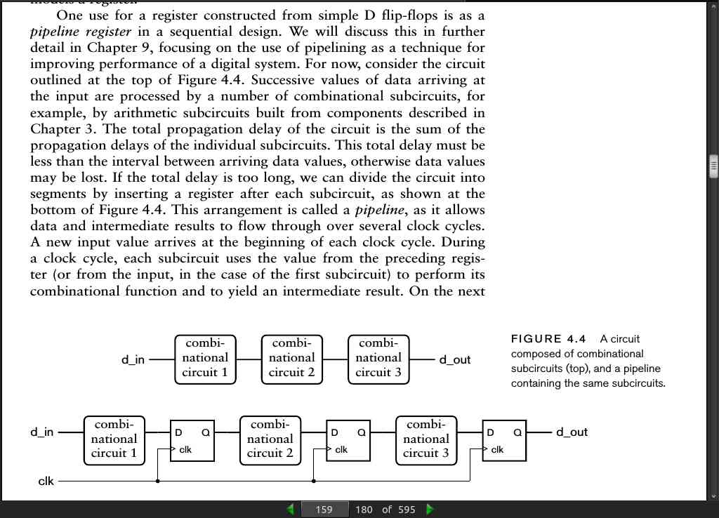
page 164:
- synchronous D flip flop
reg: process (clk) is
begin
  if rising_edge(clk) then
    if reset = '1' then
      q <= '0';
    elsif ce = '1' then
      q <= d;
    end if;
  end if;
end process reg;
- asynchronous D flip flop
reg: process (clk, reset) is
begin
  if reset = '1' then
    q <= '0';
  elsif rising_edge(clk) then
    if ce = '1' then
      q <= d;
    end if;
  end if;
end process reg;
page 168:
- We adopt the convention of appending “_n” to a name to indicate active-low logic.
page 170:
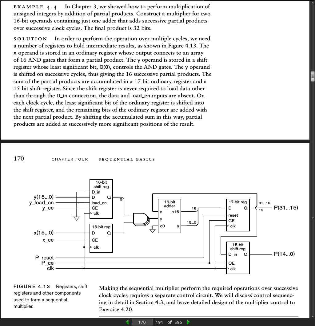
page 172:
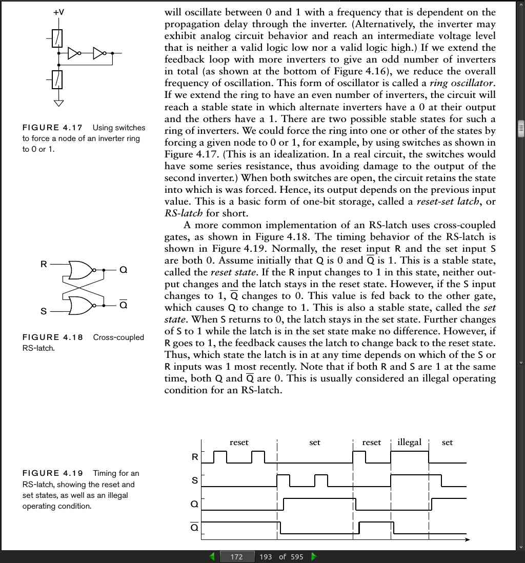
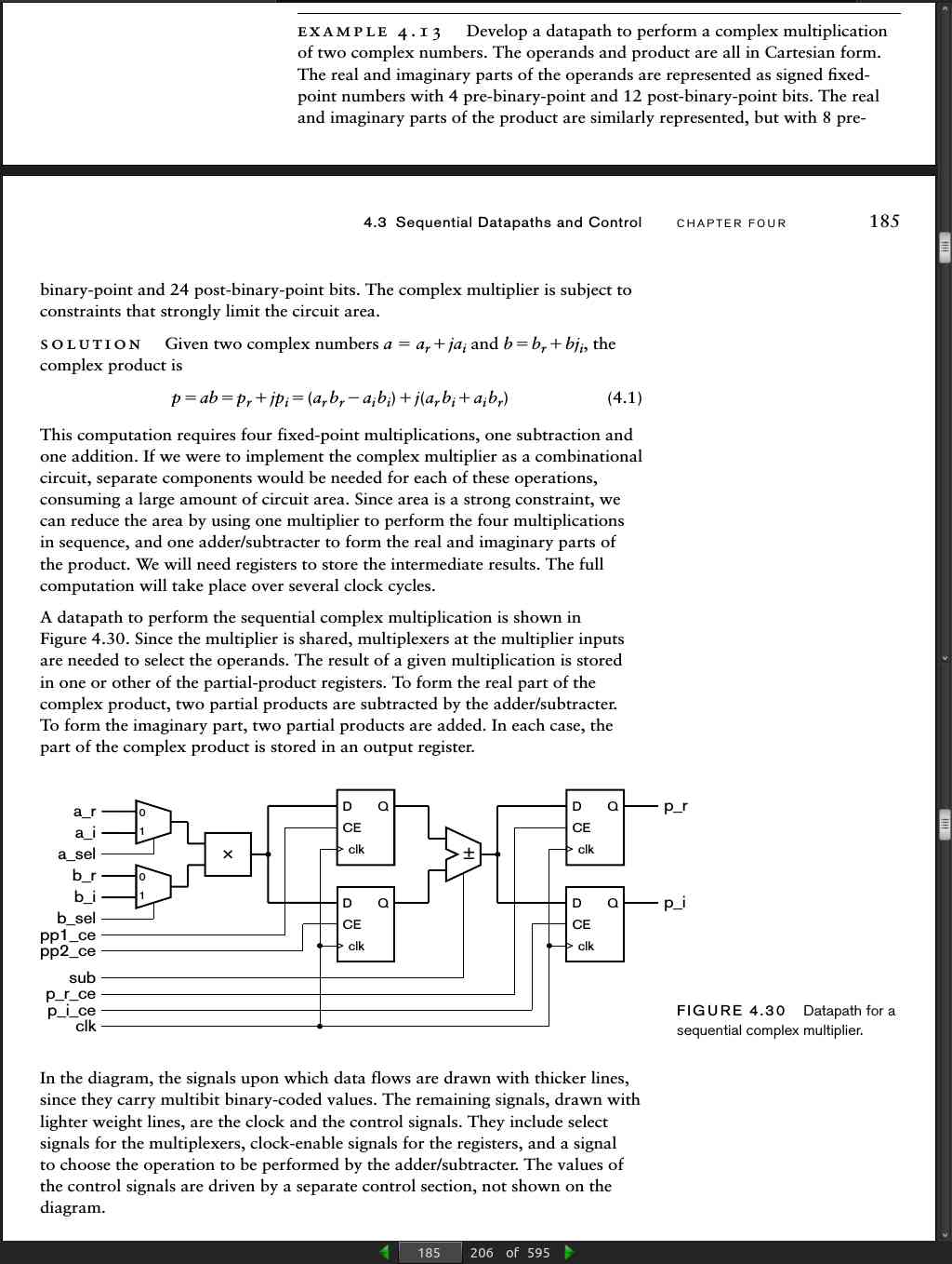
page 183:
- The main advantages of a ripple counter are that it uses much less circuitry in its implementation (since an incrementer is not required) and that it consumes less power. Hence, it is useful in those applications that are sensitive to area, cost and power and that have less stringent timing constraints. As an example, a digital alarm clock might use ripple counters to count the time, since changes occur infrequently relative to the propagation delay (seconds compared to nanoseconds).
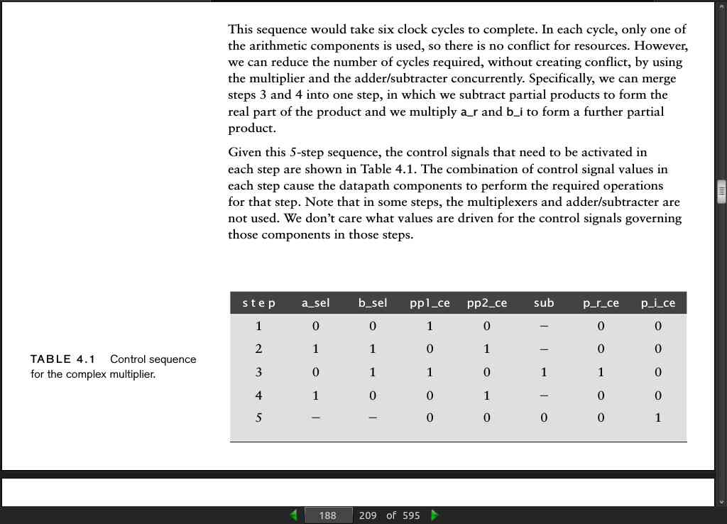
page 185:
page 187:
-
Example 4.14: Develop a VHDL model of the complex multiplier datapath.
-
Solution: We will start with the entity declaration. It includes ports for the data inputs and outputs, as well as clock and reset inputs and an input to indicate the arrival of new data. We will return to the last of these inputs later.
library ieee;
use ieee.std_logic_1164.all, ieee.fixed_pkg.all;
entity multiplier is
  port (clk, reset: in std_logic;
        input_rdy: in std_logic;
        a_r, a_i, b_r, b_i: in sfixed(3 downto –12);
        p_r, p_i: out sfixed(7 downto –24) );
end entity multiplier;

architecture rtl of multiplier is
  signal a_sel, b_sel,
         pp1_ce, pp2_ce,
         sub, p_r_ce, p_i_ce : std_logic;
  signal a_operand, b_operand : sfixed(3 downto –12);
  signal pp, pp1, pp2, sum : sfixed(7 downto –24);

begin
  a_operand <= a_r when a_sel = '0' else a_i;
  b_operand <= b_r when b_sel = '0' else b_i;
  pp <= a_operand * b_operand;

pp1_reg : process (clk) is
begin
  if rising_edge(clk) then
    if pp1_ce = '1' then
      pp1 <= pp;
    end if;
  end if;
end process pp1_reg;

pp2_reg : process (clk) is
begin
  if rising_edge(clk) then
    if pp2_ce = '1' then
      pp2 <= pp;
    end if;
  end if;
end process pp2_reg;

sum <= pp1 + pp2 when sub = '0' else pp1 – pp2;

p_r_reg : process (clk) is
begin
  if rising_edge(clk) then
    if p_r_ce = '1' then
      p_r <= sum;
    end if;
  end if;
end process p_r_reg;

p_i_reg : process (clk) is
begin
  if rising_edge(clk) then
    if p_i_ce = '1' then
      p_i <= sum;
    end if;
  end if;
end process p_i_reg;

end architecture rtl;
- Sequence of operations:
1. Multiply a_r and b_r, and store the result in partial product register 1.
2. Multiply a_i and b_i, and store the result in partial product register 2.
3. Subtract the partial product register values and store the result in the
product real part register.
4. Multiply a_r and b_i, and store the result in partial product register 1.
5. Multiply a_i and b_r, and store the result in partial product register 2.
6. Add the partial product register values and store the result in the product
imaginary part register.
page 188:
page 190:
page 191:
- We can define an enumeration type that just defines a set of values. For example, we can define an enumeration type for the states in Example 4.16 as follows:
type multiplier_state is
  (step1, step2, step3, step4, step5);

signal current_state : multiplier_state;

current_state <= step4;
page 192:
type multiplier_state is (step1, step2, step3, step4, step5);
signal current_state, next_state : multiplier_state;

state_reg : process (clk, reset) is
begin
  if reset = '1' then
    current_state <= step1;
  elsif rising_edge(clk) then
    current_state <= next_state;
  end if;
end process state_reg;

next_state_logic : process (current_state, input_rdy) is
begin
  case current_state is
    when step1 =>
      if input_rdy = '0' then
        next_state <= step1;
      else
        next_state <= step2;
      end if;
    when step2 =>
      next_state <= step3;
    when step3 =>
      next_state <= step4;
    when step4 =>
      next_state <= step5;
    when step5 =>
      next_state <= step1;
  end case;
end process next_state_logic;

output_logic : process (current_state) is
begin
  a_sel <= '0'; b_sel <= '0'; pp1_ce <= '0'; pp2_ce <= '0';
  sub <= '0'; p_r_ce <= '0'; p_i_ce <= '0';
  case current_state is
    when step1 =>
      pp1_ce <= '1';
    when step2 =>
      a_sel <= '1'; b_sel <= '1'; pp2_ce <= '1';
    when step3 =>
      b_sel <= '1'; pp1_ce <= '1'; sub <= '1'; p_r_ce <= '1';
    when step4 =>
      a_sel <= '1'; pp2_ce <= '1';
    when step5 =>
      p_i_ce <= '1';
  end case;
end process output_logic;
page 196:
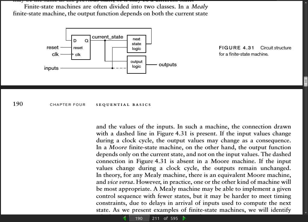
- In a Mealy finite-state machine, the output function depends on both the current state and the values of the inputs. If the input values change during a clock cycle, the output values may change as a consequence. In a Moore finite-state machine, on the other hand, the output function depends only on the current state, and not on the input values.
page 197:
-
register-transfer level (RTL) view. The word “level” refers to the level of abstraction. Register-transfer level is more abstract than a gate-level view, but less abstract than an algorithmic view.
-
setup time = t_su
-
hold time = t_h
-
clock-to-output delay = t_co
-
propagation delay = t_pd
-
clock cycle time = t_c
page 198:
t_co + t_pd + t_su < t_c
- We simply aggregate the combinational propagation delays through the combinational subcircuit and output logic to derive the inequality:
t_co + t_pd-s + t_pd-o + t_pd-c + t_su < t_c
-
Here, tpd-s is the propagation delay through the combinational subcircuit to drive the status signals, tpd-o is the propagation delay through the output logic to drive the control signals, and tpd-c is the propagation delay through the combinational subcircuit for a change in the control signal to affect the output data.
-
The path with the longest propagation delay is called the critical path. It determines the shortest possible clock cycle time for the system.
page 204:
- debounce delay of up to 10ms is common practice.
page 205:
library ieee; use ieee.std_logic_1164.all;
entity debouncer is
  port (clk, reset: in std_logic;
        pb: in std_logic;
        pb_debounced : out std_logic );
end entity debouncer;

architecture rtl of debouncer is
signal count500000 : integer range 0 to 499999;
signal clk_100Hz : std_logic;
signal pb_sampled
 : std_logic;
begin

div_100Hz : process (clk, reset) is
begin
  if reset = '1' then
    count500000 <= 499999;
  elsif rising_edge(clk) then
    if clk_100Hz = '1' then
      count500000 <= 499999;
    else
      count500000 <= count500000 – 1;
    end if;
  end if;
end process div_100Hz;

clk_100Hz <= '1' when count500000 = 0 else '0';

debounce_pb : process (clk) is
begin
  if rising_edge(clk) then
    if clk_100Hz = '1' then
      if pb = pb_sampled then
        pb_debounced <= pb;
      end if;
      pb_sampled <= pb;
    end if;
  end if;
end process debounce_pb;
end architecture rtl;
page 206:
- We might also consider implementing the debounce operation in software run on an embedded processor, if the application requires a processor to be included anyway.
page 213:
- A digital system, in general, consists of a datapath and a control section. The datapath contains combinational subcircuits for operating on data and registers for storing data. The control section sequences operations in the datapath by activating control signals at various times. The control section uses status signals to influence the control sequence.
page 214:
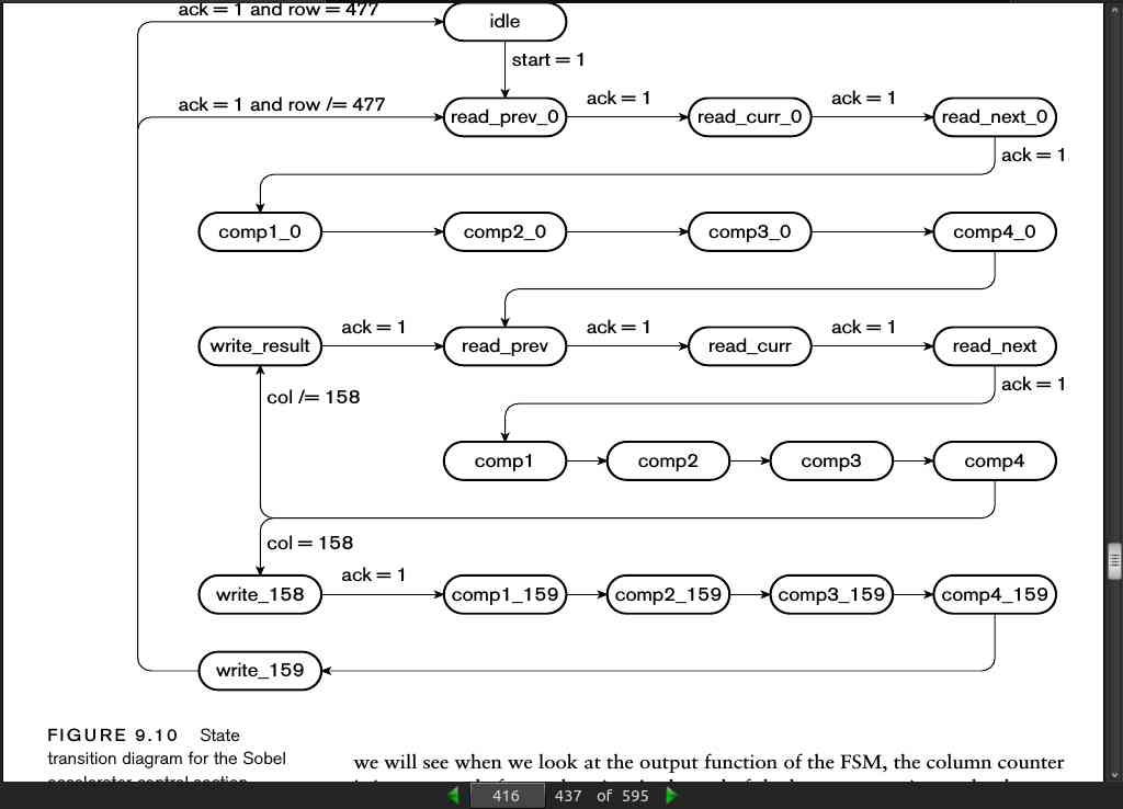
- A state transition diagram represents a finite state machine with bubbles for states, arcs for transitions, and labels for input conditions and output values. Labels for Moore-style outputs are written in the bubbles, and labels for Mealy-style outputs are written on arcs.
page 215:
- A Guide to Debouncing, Jack G. Ganssle, The Ganssle Group, 2004, www.ganssle.com/debouncing.pdf. Presents empirical data on switch bounce behavior, and describes hardware and software approaches to debouncing.
· CHAPTER 5: Memories
page 228:
- Memory components implemented as packaged integrated circuits, for use in a larger system implemented on a printed circuit board, typically do have tristate data outputs or tristate bidirectional data input/outputs. On the other hand, memory blocks provided within ASICs and FPGAs typically do not have tristate data connections, since tristate buses present some design and verification challenges in those fabrics.
page 229:
- In high performance systems, we can connect multiple memory components together in ways that permit multiple operations to proceed concurrently, thus increasing the total number of operations completed per second. These schemes usually involve organizing the memory into a number of banks, each of which can perform an operation in parallel with other banks. Successive addresses are assigned to different banks, since, in many systems, locations are often accessed in order. As an example, a system with four banks would assign locations 0, 4, 8, … to bank 0; locations 1, 5, 9, … to bank 1; 2, 6, 10, … to bank 2; and 3, 7, 11, … to bank 3. When a read operation is required for location 4, bank 0 would read that location. Moreover, the other banks would start a read, prefetching locations 5, 6 and 7. By the time a read operation is required for these locations (assuming access in order), the data would already be available from the memory.
page 231:
- [with asynchronous SRAM] we can also perform back-to-back read operations simply by changing the address value. The read operation is essentially a combinational operation, involving decoding the address and multiplexing the selected latch-cell’s value onto the data outputs. Changing the address simply causes a different cell’s value to appear on the outputs after a propagation delay.
page 232:
- SSRAM = synchronous static RAM
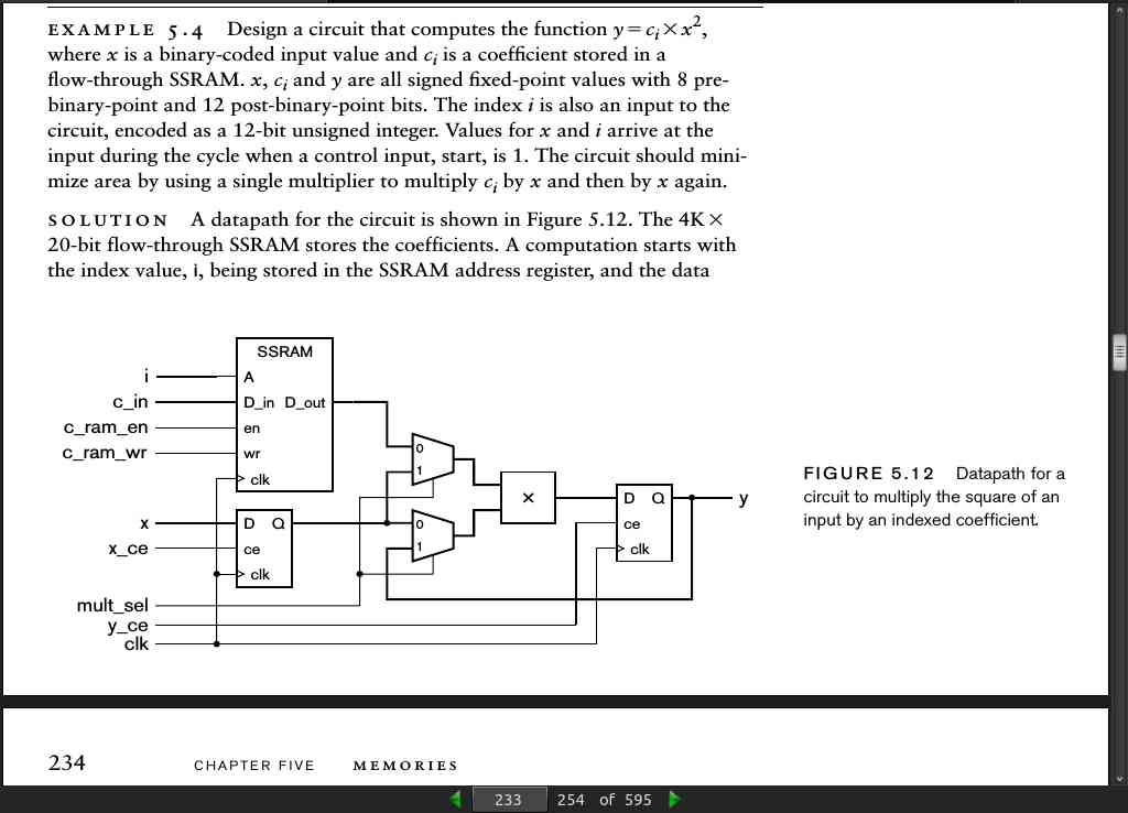
page 233:
page 236:
- to model a register, we declare a signal to represent the stored register value and assign a new value to it on a rising clock edge. We can extend this approach to model an SSRAM in VHDL. We need to declare a signal that represents all of the locations in the memory. The way to do this is to declare an array type, which represents a collection of values, each with an index that corresponds to its location in the array. We then declare a signal of the array type to represent the stored data. For example, to model a 4K ϫ 16-bit memory, we would write the following declarations:
type RAM_4Kx16 is array (0 to 4095) of std_logic_vector(15 downto 0);
signal data_RAM : RAM_4Kx16;
- a process to model a flow-through SSRAM based on the signal declaration above is:
data_RAM_flow_through : process (clk) is
begin
  if rising_edge(clk) then
    if en = '1' then
      if wr = '1' then
        data_RAM(to_integer(a)) <= d_in; d_out <= d_in;
      else
        d_out <= data_RAM(to_integer(a));
      end if;
    end if;
  end if;
end process data_RAM_flow_through;
page 241:
- Example 5.7 Develop a VHDL model of a dual-port, 4K ϫ 16-bit flow-through SSRAM. One port allows data to be written and read, while the other port only allows data to be read. Solution: The entity declaration is:
library ieee;
use ieee.std_logic_1164.all, ieee.numeric_std.all;

entity dual_port_SSRAM is
  port (clk: in std_logic;
        en1, wr1 : in std_logic;
        a1: in unsigned(11 downto 0);
        d_in1: in std_logic_vector(15 downto 0);
        d_out1: out std_logic_vector(15 downto 0);
        en2: in std_logic;
        a2: in unsigned(11 downto 0);
        d_out2: out std_logic_vector(15 downto 0) );
end entity dual_port_SSRAM;

architecture synth of dual_port_SSRAM is
  type RAM_4Kx16 is array (0 to 4095) of std_logic_vector(15 downto 0);
  signal data_RAM : RAM_4Kx16;
begin

read_write_port : process (clk) is
begin
  if rising_edge(clk) then
    if en1 = '1' then
      if wr1 = '1' then
        data_RAM(to_integer(a1)) <= d_in1; d_out1 <= d_in1;
      else
        d_out1 <= data_RAM(to_integer(a1));
      end if;
    end if;
  end if;
end process read_write_port;

read_only_port : process (clk) is
begin
  if rising_edge(clk) then
    if en2 = '1' then
      d_out2 <= data_RAM(to_integer(a2));
    end if;
  end if;
end process read_only_port;
end architecture synth;
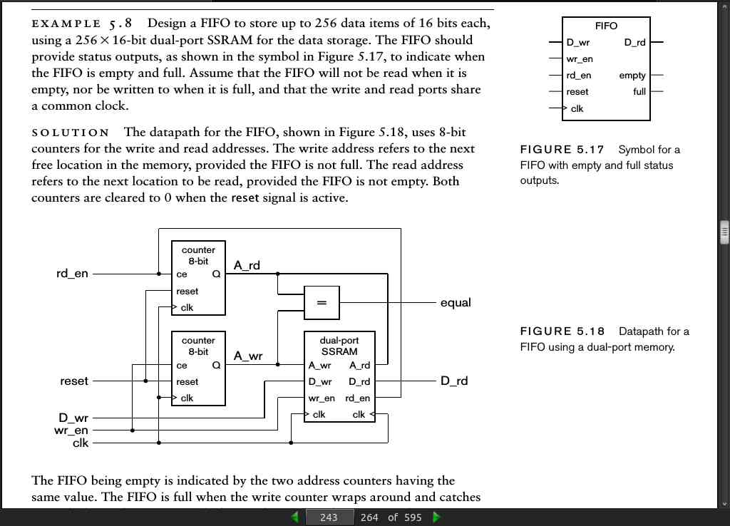
page 243:
page 246:
-
DRAM = (asynchronous) dynamic RAM, needs refreshed (~ every 64ms)
-
SDRAM = synchronous dynamic RAM
page 247:
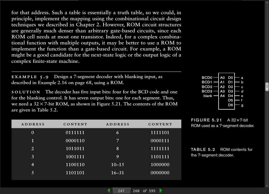
- Example 5.10 Develop a VHDL model of the 7-segment decoder of Example 5.9. Solution: The entity is the same as in Example 2.16. The architecture is
library ieee; use ieee.numeric_std.all;
architecture ROM_based of seven_seg_decoder is
  type ROM_array is array (0 to 31) of std_logic_vector(7 downto 1);
  constant ROM_content : ROM_array :=
    ( 0 => "0111111", 1 => "0000110",
      2 => "1011011", 3 => "1001111",
      4 => "1100110", 5 => "1101101",
      6 => "1111101", 7 => "0000111",
      8 => "1111111", 9 => "1101111",
      10 to 15 => "1000000",
      16 to 31 => "0000000" );

begin
  seg <= ROM_content(to_integer(unsigned(blank & bcd)));
end architecture ROM_based;
page 248:
- In FPGA fabrics that provide SSRAM blocks, we can use an SSRAM block as a ROM. We simply declare a constant for the data instead of a signal, as in Example 5.10, and modify the process template for the memory to omit the part that updates the memory content. For example,
type ROM_512x20 is array (0 to 511) of std_logic_vector(19 downto 0);
constant data_ROM : ROM_512x20 := (X"00000", X"0126F", ...);

FPGA_ROM : process (clk) is
begin
  if rising_edge(clk) then
    if en = '1' then
      d_out <= data_ROM(to_integer(a));
    end if;
  end if;
end process FPGA_ROM;
page 252:
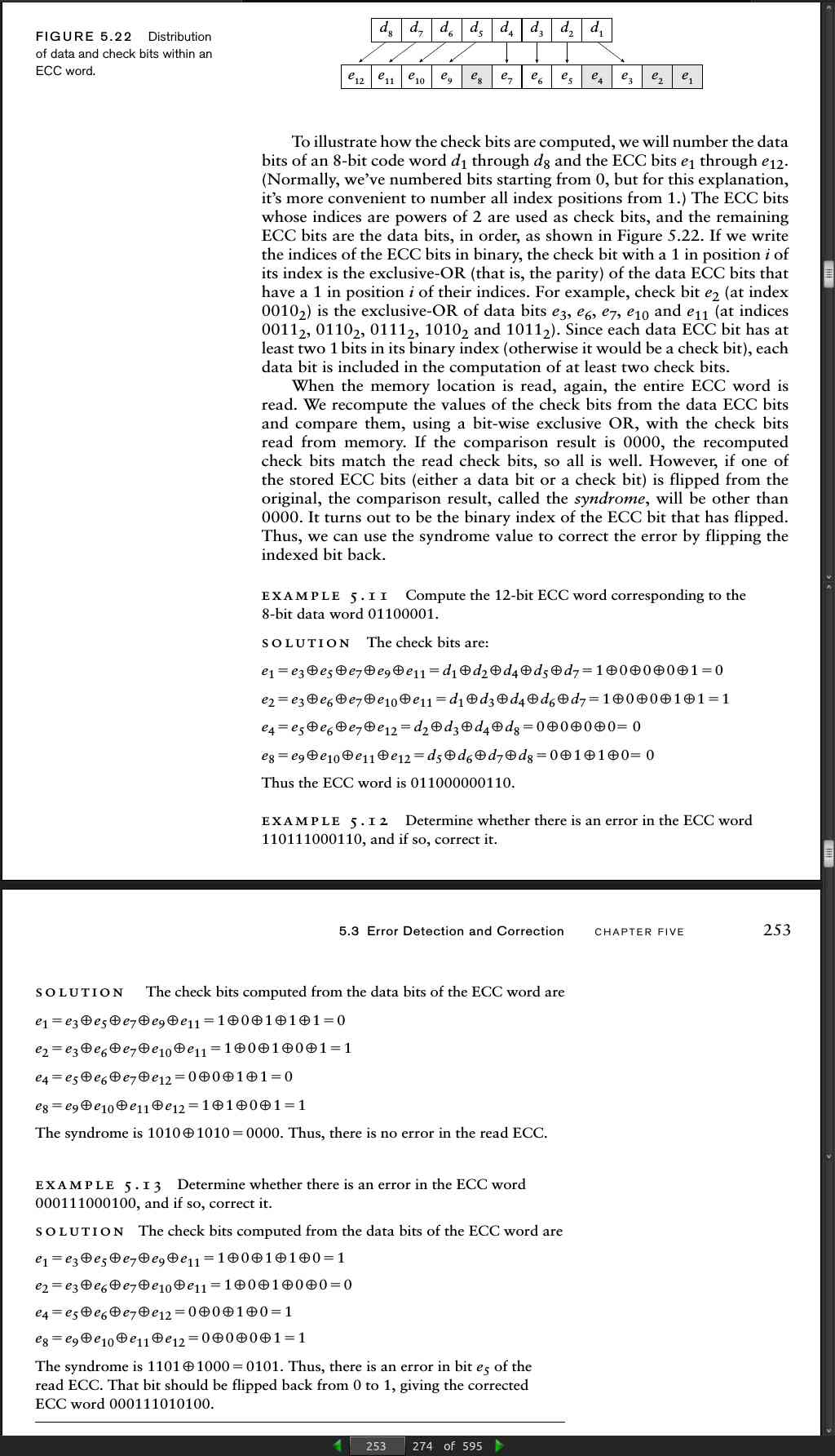
- One scheme for doing this is to use a form of error correcting code (ECC) known as a Hamming code.
page 253:
- Note that we have assumed that only one bit of the stored ECC word could be in error. If two or more bits flip, the checking process may incorrectly identify a single bit as having flipped, or it may yield an invalid syndrome. The problem arises from the fact that we have insufficient invalid code words to distinguish between single-bit errors and double-bit errors. A simple remedy is to add further check bits. If we add a check bit that is the exclusive-OR of all of the data bits, the resulting error-checking code allows us to correct any single-bit error and to detect (but not correct) any double-bit error. If we assume that errors are independent, the probability of a double-bit error is very low, so this scheme suffices in many applications.
page 254:
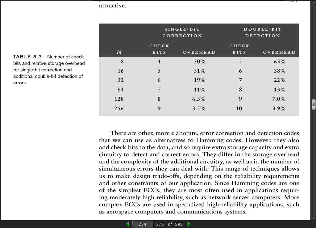
- Since Hamming codes are one of the simplest ECCs, they are most often used in applications requiring moderately high reliability, such as network server computers. More complex ECCs are used in specialized high-reliability applications, such as aerospace computers and communications systems.
· CHAPTER 6: Implementation Fabrics
page 267:
-
The development of IC technology beyond the LSI level led to very large scale integrated (VLSI) circuits.
-
We use the term application-specific integrated circuit, or ASIC, to refer to an IC manufactured for a particular application.
page 276:
page 277:
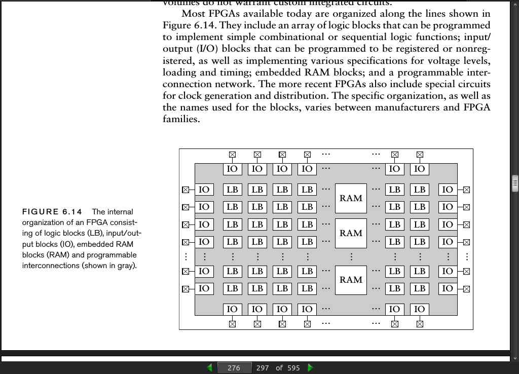
- In many FPGA components, the basic elements within logic blocks are small 1-bit-wide asynchronous RAMs called lookup tables (LUTs). The LUT address inputs are connected to the inputs of the logic block. The content of an LUT determines the values of a Boolean function of the inputs, in much the same way as we discussed in Section 5.2.5. By programming the LUT content differently, we can implement any Boolean function of the inputs. The logic blocks also contain one or more flip- flops and various multiplexers and other logic for selecting data sources and for connecting data to adjacent logic blocks.
page 285:
- In common PCB materials, the maximum propagation speed is approximately half the speed of light in a vacuum. Since the latter is 3 x 10^-8 m/s^-1, we can use 150mm per nanosecond as a good rule of thumb for signal propagation along a PCB trace. For low speed designs and small PCBs, this element of total path delay is insignificant. However, for high-speed designs, particularly for signals on critical timing paths, it is significant. Two cases in point are the routing of clock signals and parallel bus signals.
page 288:
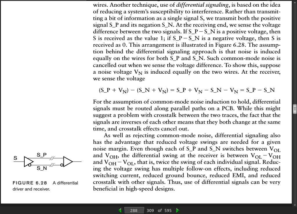
-
Another technique, use of differential signaling, is based on the idea of reducing a system’s susceptibility to interference. Rather than transmitting a bit of information as a single signal S, we transmit both the positive signal S_P and its negation S_N. At the receiving end, we sense the voltage difference between the two signals. If S_P
-
S_N is a positive voltage, then S is received as the value 1; if S_P - S_N is a negative voltage, then S is received as 0.
-
For the assumption of common-mode noise induction to hold, differential signals must be routed along parallel paths on a PCB. While this might suggest a problem with crosstalk between the two traces, the fact that the signals are inverses of each other means that they both change at the same time, and crosstalk effects cancel out.
· CHAPTER 7: Processor Basics
page 294:
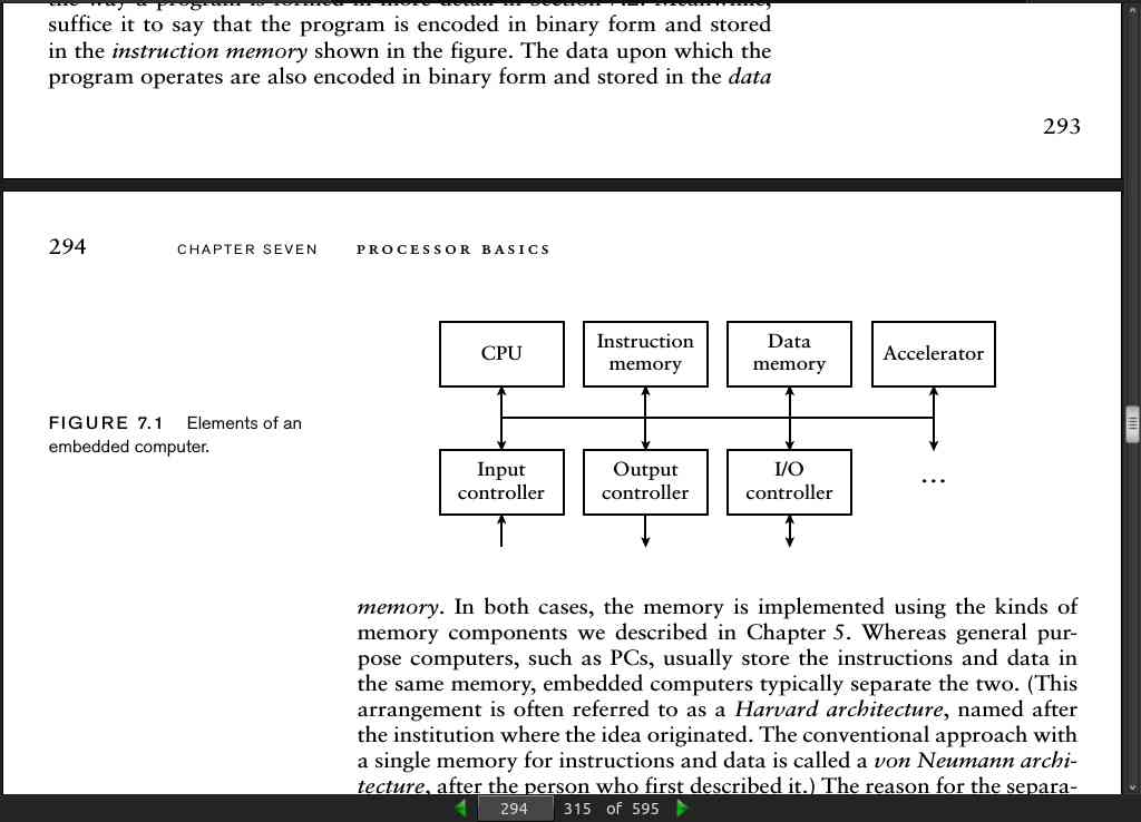
- Whereas general purpose computers, such as PCs, usually store the instructions and data in the same memory, embedded computers typically separate the two. (This arrangement is often referred to as a Harvard architecture, named after the institution where the idea originated. The conventional approach with a single memory for instructions and data is called a von Neumann architecture
page 295:
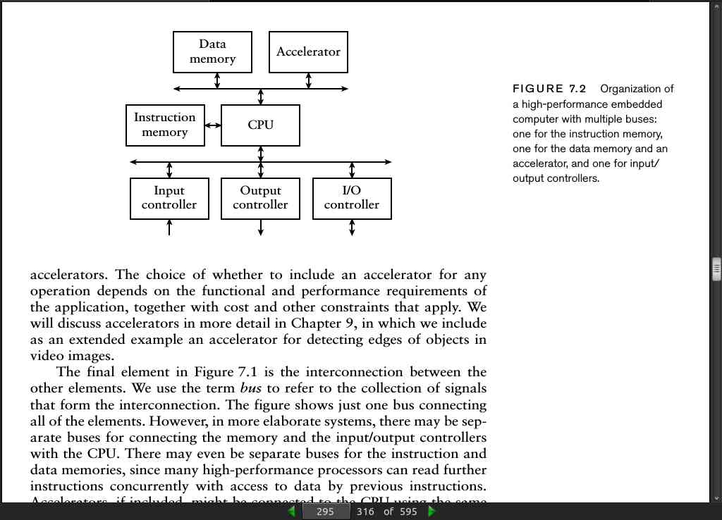
page 296:
- CPU can be implemented as a soft core using the programmable resources of the FPGA. FPGA vendors provide soft core processor designs that users can include as part of their system. Examples include the MicroBlaze core from Xilinx, the Nios-II core from Altera, and the ARM core from Actel.
page 297:
- A microprocessor is a CPU in a package by itself, whereas a microcontroller includes a CPU, instruction and data memory, and I/O controllers all in the one package.
page 298:
- The terms “little endian” and “big endian” originated in Jonathan Swift’s Gulliver’s Travels, in which the people of two countries fight over which end of their breakfast eggs should be cut open.
page 314:
- Example 7.10 The memory interface signals of the Gumnut core are described in the following VHDL entity declaration:
library ieee;
use ieee.std_logic_1164.all, ieee.numeric_std.all;
entity gumnut is
port (clk_i: in std_logic;
      rst_i: in std_logic;
      inst_cyc_o: out std_logic;
      inst_stb_o: out std_logic;
      inst_ack_i: in std_logic;
      inst_adr_o: out unsigned(11 downto 0);
      inst_dat_i: in std_logic_vector(17 downto 0);
      data_cyc_o: out std_logic;
      data_stb_o: out std_logic;
      data_we_o: out std_logic;
      data_ack_i: in std_logic;
      data_adr_o: out unsigned(7 downto 0);
      data_dat_o: out std_logic_vector(7 downto 0);
      data_dat_i: in std_logic_vector(7 downto 0)
     );
end entity gumnut;
-
Show how to include an instance of the Gumnut core in a VHDL model of an embedded system with a 2K ϫ 18-bit instruction memory and a 256 ϫ 8-bit data memory.
-
Solution The ports in the entity declaration can interface with the control signals of a flow-through SSRAM and a ROM implemented using FPGA SSRAM blocks, as described in Sections 5.2.2 and 5.2.5. In our architecture for our embedded system, we include the necessary signals to connect to an instance of the Gumnut entity, and use the signals in processes for the instruction and data memories. The architecture is
architecture rtl of embedded_gumnut is
type ROM_2Kx18 is array (0 to 2047) of std_logic_vector(17 downto 0);
constant instr_ROM : ROM_2Kx18 := ( ... );
type RAM_256x8 is array (0 to 255) of std_logic_vector(7 downto 0);

signal data_RAM : RAM_256x8;
signal clk : std_logic;
signal rst : std_logic;
signal inst_cyc_o : std_logic;
signal inst_stb_o : std_logic;
signal inst_ack_i : std_logic;
signal inst_adr_o : unsigned(11 downto 0);
signal inst_dat_i : std_logic_vector(17 downto 0);
signal data_cyc_o : std_logic;
signal data_stb_o : std_logic;
signal data_we_o : std_logic;
signal data_ack_i : std_logic;
signal data_adr_o : unsigned(7 downto 0);
signal data_dat_o : std_logic_vector(7 downto 0);
signal data_dat_i : std_logic_vector(7 downto 0);

begin
  CPU : entity work.gumnut
    port map (clk_i => clk,
              rst_i => rst,
              inst_cyc_o => inst_cyc_o,
              inst_stb_o => inst_stb_o,
              inst_ack_i => inst_ack_i,
              inst_adr_o => inst_adr_o,
              inst_dat_i => inst_dat_i,
              data_cyc_o => data_cyc_o,
              data_stb_o => data_stb_o,
              data_we_o => data_we_o,
              data_ack_i => data_ack_i,
              data_adr_o => data_adr_o,
              data_dat_o => data_dat_o,
              data_dat_i => data_dat_i
             );

  IMem : process (clk) is
    begin
    if rising_edge(clk) then
      if inst_cyc_o = '1' and inst_stb_o = '1' then
        inst_dat_i <= instr_ROM(to_integer(inst_adr_o(10 downto 0)));
        inst_ack_i <= '1';
      else
        inst_ack_i <= '0';
      end if;
    end if;
    end process IMem;

  DMem : process (clk) is
  begin
  if rising_edge(clk) then
    if data_cyc_o = '1' and data_stb_o = '1' then
      if data_we_o = '1' then
        data_RAM(to_integer(data_adr_o)) <= data_dat_o;
        data_dat_i <= data_dat_o;
        data_ack_i <= '1';
      else
        data_dat_i <= data_RAM(to_integer(data_adr_o));
        data_ack_i <= '1';
      end if;
    end if;
  end if;
  end process DMem;

end architecture rtl;
page 320:
- Operation of a cache is predicated on the principle of locality, which involves two important observations about the way programs access memory. The first is that a small proportion of instructions and data account for the majority of memory accesses over a given interval of time. The second is that those items stored in locations adjacent to a recently accessed item are likely to be accessed next.
page 321:
- we divide the collection of locations in main memory into fixed-sized blocks, often called lines, and copy whole lines at a time from main memory into the cache memory. When the processor requests access to a given memory location, the cache checks whether it already has a copy of the line containing the requested item. If so, the cache has a hit, and it can quickly satisfy the processor’s request. If not, the cache has a miss, and must cause the processor to wait. The cache then copies the line containing the requested item from main memory into the cache memory.
page 324:
- Computers as Components: Principles of Embedded Computing System Design, Wayne Wolf, Morgan Kaufmann Publishers, 2005. A more advanced reference on embedded systems design, covering CPU and DSP instruction sets, embedded systems platforms, and embedded software design.
· CHAPTER 8: I/O Interfacing
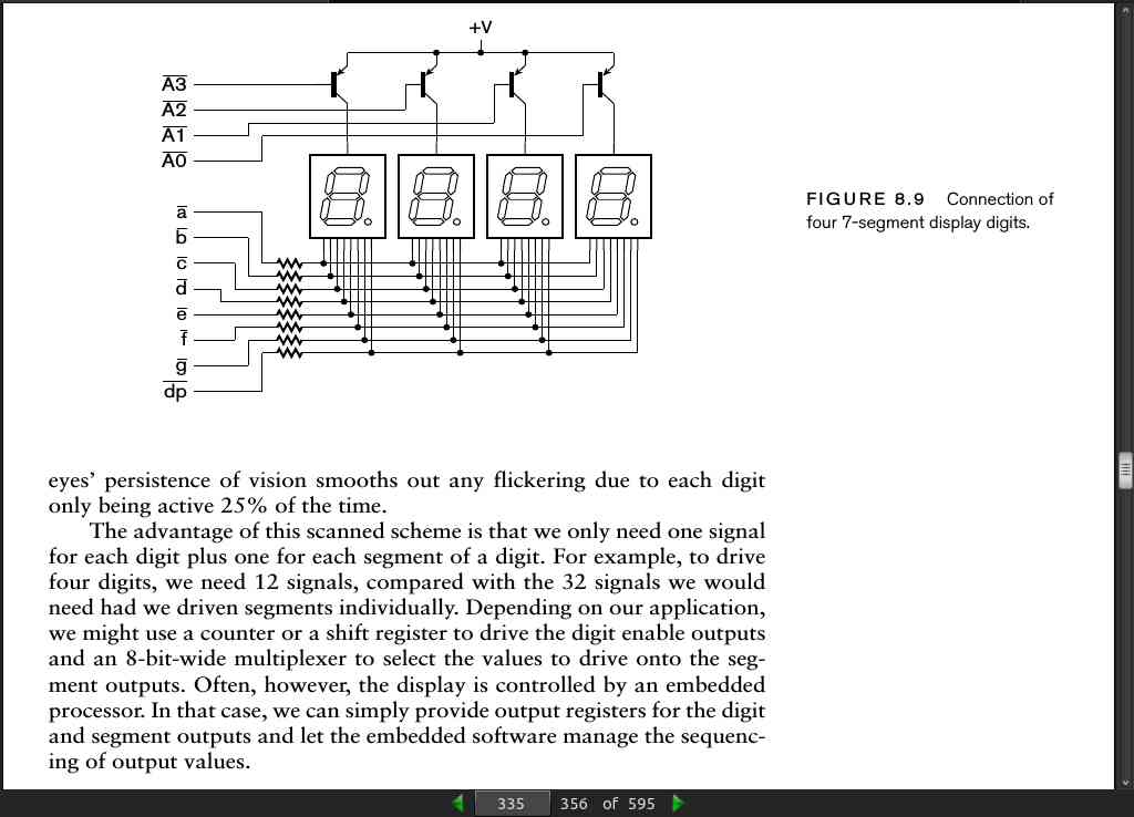
page 335:
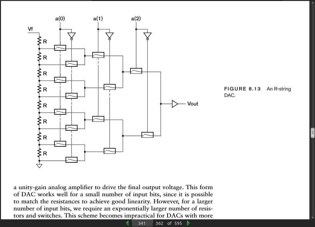
page 341:
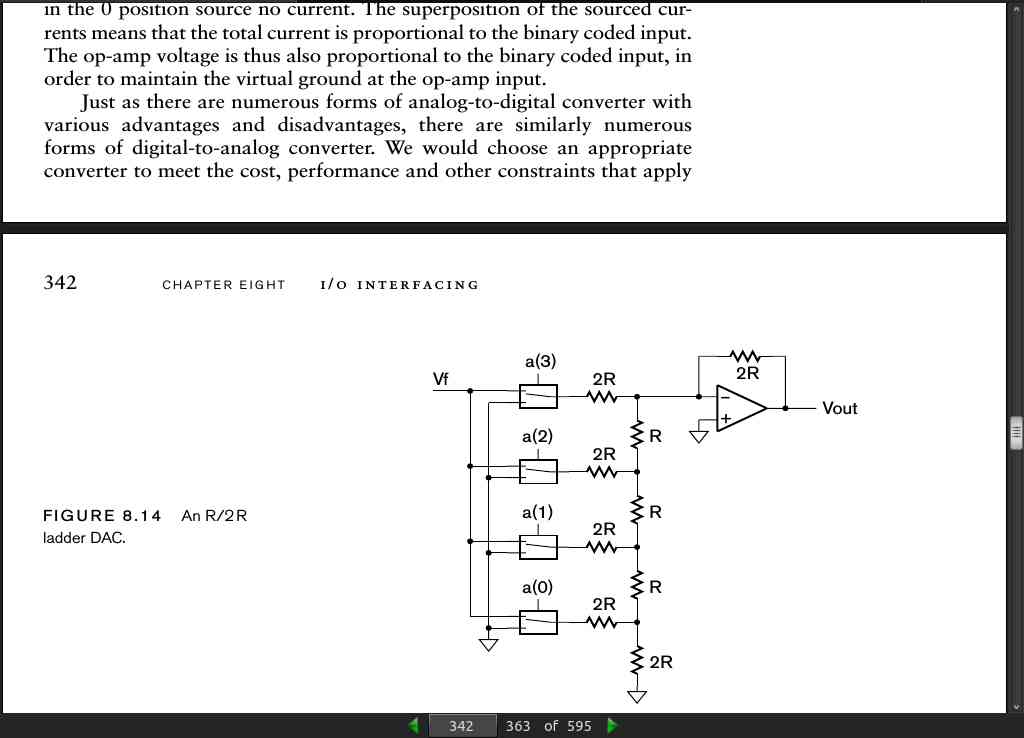
page 342:
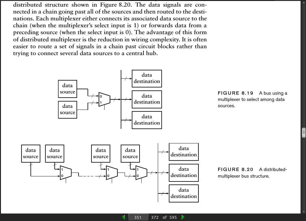
page 351:
page 356:
-
the safest approach when designing control for tristate buses is to include a margin of dead time between different data sources driving the bus. A conservative approach is to defer enabling the next driver until the clock cycle after that in which the previous driver is disabled.
-
not all implementation fabrics provide tristate drivers. For example, many FPGA devices do not provide tristate drivers for internal connections, and only provide them for external connections with other chips. If we want to design a circuit that can be implemented in different fabrics with minimal change, it is best to avoid tristate buses.
page 366:
- We sometimes use the term serializer/deserializer, or serdes, for shift registers
page 368:
- scheme for synchronizing a serial transmitter and receiver involves combining a clock with the data on the same signal wire. This avoids the need for tight clock synchronization, since there is an indication of when each bit arrives. As an example of such a scheme, we will describe Manchester encoding.
page 369:
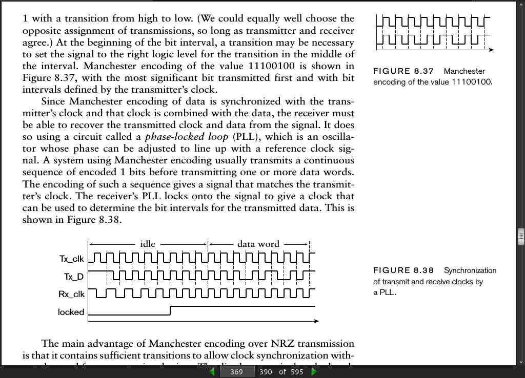
page 370:
- Serial transmission in RS232 interfaces uses NRZ encoding with start and stop bits for synchronization. Data is usually transmitted with the least significant bit first
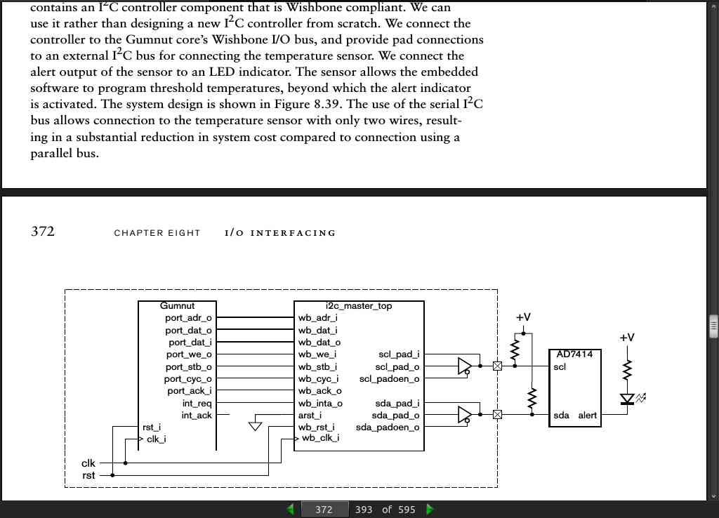
page 372:
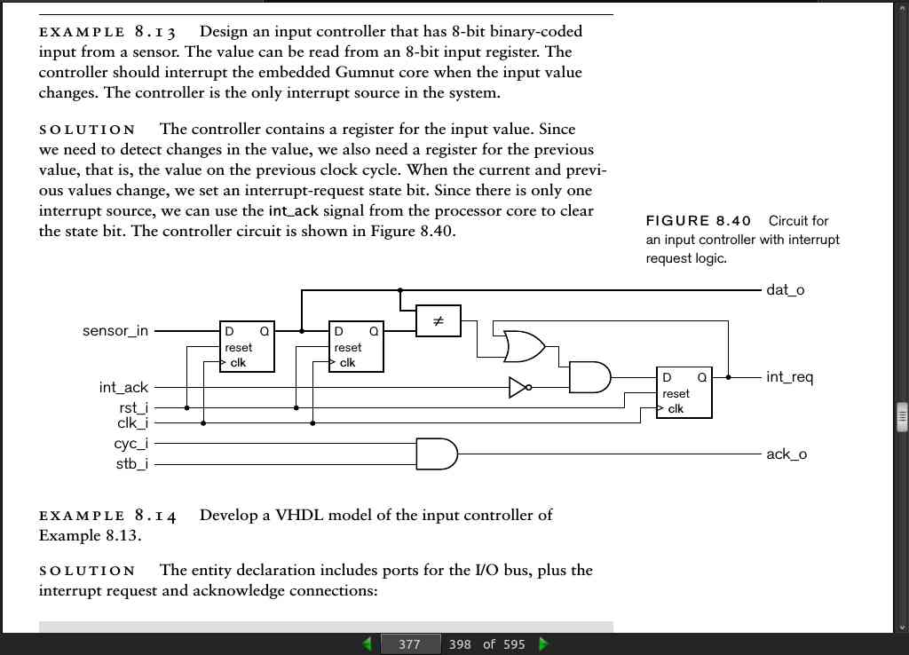
page 377:
page 378:
library ieee;
use ieee.std_logic_1164.all;
entity sensor_controller is
port (clk_i, rst_i : in std_logic;
      cyc_i, stb_i : in std_logic;
      ack_o : out std_logic;
      dat_o : out std_logic_vector(7 downto 0);
      int_req : out std_logic;
      int_ack : in std_logic;
      sensor_in : in std_logic_vector(7 downto 0) );
end entity sensor_controller;

architecture rtl of sensor_controller is
signal prev_data, current_data : std_logic_vector(7 downto 0);
signal current_int_req : std_logic;

begin
data_regs : process (clk_i) is
begin
  if rising_edge(clk_i) then
    if rst_i = '1' then
      prev_data <= "00000000";
      current_data <= "00000000";
    else
      prev_data <= current_data;
      current_data <= sensor_in;
    end if;
  end if;
end process data_regs;

int_state : process (clk_i) is
begin
  if rising_edge(clk_i) then
    if rst_i = '1' then
      current_int_req <= '0';
    else
      case current_int_req is
        when '0' =>
          if current_data /= prev_data then
            current_int_req <= '1';
          end if;
        when others =>
          if int_ack = '1' then
            current_int_req <= '0';
          end if;
      end case;
    end if;
  end if;
end process int_state;

dat_o <= current_data;
int_req <= current_int_req;
ack_o <= cyc_i and stb_i;
end architecture rtl;
page 381:
-
Example 8.16 Develop a VHDL model for a real-time clock controller for the Gumnut processor. The controller has a 10μs time base derived from a 50MHz system clock, and an 8-bit output register for the value to load into the counter. A write operation to the output register causes the counter to be loaded. After the counter reaches 0, it reloads the value from the output register and requests an interrupt. The controller has an input register for reading the current count value. The counter also has a 1-bit control output register. When bit 0 of the register is 0, interrupts from the controller are masked, and when it is 1, they are enabled. The counter has a status register, in which bit 0 is 1 when the counter has reached 0 and been reloaded, or 0 otherwise. Other bits of the register are read as 0. Reading the register has the side effect of acknowledging a requested interrupt and clearing bit 0. The counter output and input registers are located at the base port address, and the control and status registers are at offset 1 from the base port address.
-
Solution The entity declaration for the controller has ports for the I/O bus, and uses the stb_i port for the decoded base port address:
library ieee;
use ieee.std_logic_1164.all, ieee.numeric_std.all;
entity real_time_clock is
  port (clk_i, rst_i : in std_logic; -- 50 MHz clock
        cyc_i, stb_i, we_i : in std_logic;
        ack_o : out std_logic;
        adr_i : in std_logic;
        dat_i : in unsigned(7 downto 0);
        dat_o : out unsigned(7 downto 0);
        int_req : out std_logic );
end entity real_time_clock;

architecture rtl of real_time_clock is
  constant clk_freq : natural := 50000000;
  constant timebase_freq : natural := 100000;
  constant timebase_divisor : natural := clk_freq / timebase_freq;
  signal count_value : unsigned(7 downto 0);
  signal trigger_interrupt : std_logic;
  signal int_enabled, int_triggered : std_logic;

begin
  counter : process (clk_i) is
    variable timebase_count : natural range 0 to timebase_divisor – 1;
    variable count_start_value : unsigned(7 downto 0);

  begin
    if rising_edge(clk_i) then
      if rst_i = '1' then
        timebase_count := 0;
        count_start_value := "00000000";
        count_value <= "00000000";
        trigger_interrupt <= '0';
      elsif cyc_i = '1' and stb_i = '1' and adr_i = '0' and we_i = '1' then
        timebase_count := 0;
        count_start_value := dat_i;
        count_value <= dat_i;
        trigger_interrupt <= '0';
      elsif timebase_count = timebase_divisor — 1 then
        timebase_count := 0;
        if count_value = "00000000" then
          count_value <= count_start_value;
          trigger_interrupt <= '1';
        else
          count_value <= count_value — 1;
          trigger_interrupt <= '0';
      end if;
    else
      timebase_count := timebase_count + 1;
      trigger_interrupt <= '0';
    end if;
  end if;
end process counter;

control_reg : process (clk_i) is
begin
  if rising_edge(clk_i) then
    if rst_i = '1' then
      int_enabled <= '0';
    elsif cyc_i = '1' and stb_i = '1' and adr_i = '1' and we_i = '1' then
      int_enabled <= dat_i(0);
    end if;
  end if;

end process control_reg;

int_reg : process (clk_i) is
begin
  if rising_edge(clk_i) then
    if rst_i = '1' or (cyc_i = '1' and stb_i = '1' and adr_i = '1' and we_i = '0') then
      int_triggered <= '0';
    elsif trigger_interrupt = '1' then
      int_triggered <= '1';
    end if;
  end if;
end process int_reg;

dat_o <= count_value when adr_i = '0' else "0000000" & int_triggered;
int_req <= int_triggered and int_enabled;
ack_o <= cyc_i and stb_i;
end architecture rtl;
page 387:
-
Resistive pull-ups are modeled in VHDL using the ‘H’ std_logic value.
-
OpenCores, www.opencores.org. From the website’s FAQ, “OpenCores is a loose collection of people who are interested in developing hardware, with a similar ethos to the free software movement.” The website hosts a repository of freely reusable core designs, many of which are compatible with the Wishbone bus.
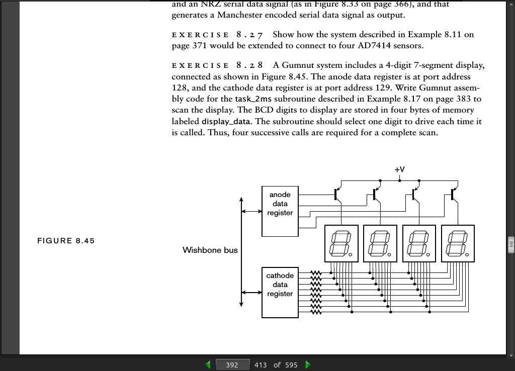
page 392:
· CHAPTER 9: Accelerators
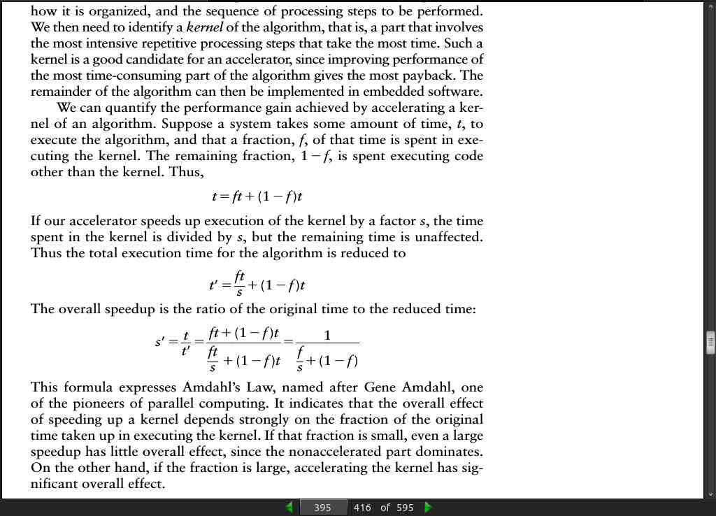
page 395:
page 396:
-
There are two main schemes for implementing parallelism in accelerators. The first of these is simply to replicate components that perform a given step so that they operate on different elements of data. The speedup achieved through replication, compared to using just a single component, is ideally equal to the number of times the component is replicated. This scheme suits applications in which steps can be performed independently on the different data elements.
-
The second scheme for implementing parallelism is to break a larger computational step into a sequence of simpler steps, and to perform the sequence in a pipeline, as shown in Figure 9.1. The pipeline stages perform their simple steps in parallel, each operating on a different data element or an intermediate result produced by the preceding stages. The overall computation by the pipeline for a given data element takes approximately the same time as a nonpipelined chain of components. However, provided we can supply data to the pipeline input and accept data at the pipe- line output on every clock cycle, the pipeline completes one computation every cycle. Thus, the speedup compared to the nonpipelined chain is ideally equal to the number of stages. This scheme suits applications that involve complex processing steps that can be broken down into simpler sequences with each step depending only on the results of earlier steps.
-
we can have replicated pipelines, giving the benefit of both schemes.
page 400:
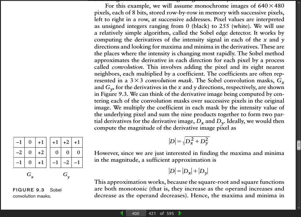
- The Sobel method approximates the derivative in each direction for each pixel by a process called convolution. This involves adding the pixel and its eight nearest neighbors, each multiplied by a coefficient. The coefficients are often rep- resented in a 3x3 convolution mask. The Sobel convolution masks, Gx and Gy , for the derivatives in the x and y directions, respectively, are shown in Figure 9.3.
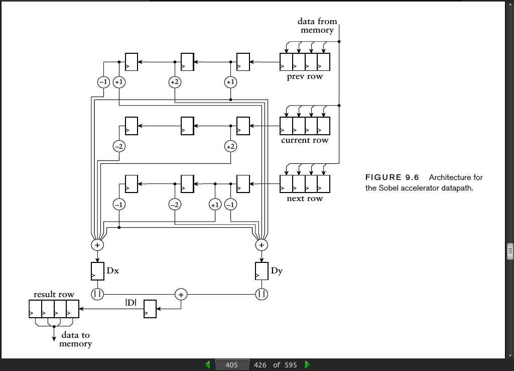
page 405:
page 416:
 “width:33%; margin:1%;”)}}
page 436:
- Computers as Components: Principles of Embedded Computing System Design, Wayne Wolf, Morgan Kaufmann Publishers, 2005. Includes a discussion of accelerators in the context of embedded hardware and software design, with a video-processing accelerator as a case study.
· CHAPTER 10: Design Methodology
page 460:
- Performance and timing are essentially the inverses of each other. We usually think of performance in terms of the number of operations completed per unit time. The inverse of this is the time taken to complete an operation.
page 463:
page 465:
- the greater the fanout load connected to a circuit, the greater the power required to switch the load between high and low logic levels.
Appendix C
page 564:
- Finite State Machine:
type state_type is (state1, state2, state3, state4);
signal current_state, next_state : state_type;


state_reg : process (clock) is
begin
  if rising_edge(clock) then
    if reset = '1' then
      current_state <= initial-state;
    else
      current_state <= next_state;
    end if;
  end if;
end process state_reg;

next_state_logic : process (current_state,
input-1, input-2, ...) is
begin
  case current_state is
    when state1 =>
      if condition-1 then
        next_state <= state-value;
      elsif condition-2 then
        next_state <= state-value;
        ...
      else
        next_state <= state-value;
      end if;
    when state2 =>
    ...
  end case;
end process next_state_logic;

output_logic : process (current_state, input-1, input-2, ...) is
begin
  case current_state is
    when state1 =>
      moore-output-1 <= value; moore-output-2 <= value; ...
      if condition-1 then
        mealy-output-1 <= value; mealy-output-2 <= value; ...
      elsif condition-2 then
        mealy-output-1 <= value; mealy-output-2 <= value; ...
        ...
      else
        mealy-output-1 <= value; mealy-output-2 <= value; ...
      end if;
    when state2 =>
      ...
  end case;
end process output_logic;

fsm_logic : process (current_state, input-1, input-2, ...) is
begin
  case current_state is
    when state1 =>
      if condition-1 then
        next_state <= state-value;
        mealy-output-1 <= value; mealy-output-2 <= value; ...
      elsif condition-2 then
        next_state <= state-value;
        mealy-output-1 <= value; mealy-output-2 <= value; ...
        ...
      else
        next_state <= state-value;
        mealy-output-1 <= value; mealy-output-2 <= value; ...
      end if;
      moore-output-1 <= value; moore-output-2 <= value; ...
    when state2 =>
      ...
  end case;
end process fsm_logic;
page 567:
- For example, to describe a flow-through SSRAM, we can use a process of the form:
process-name : process (clock) is
begin
  if rising_edge(clock) then
    if enable = '1' then
      if write = '1' then
        data_ram(to_integer(address)) <= data-in;
        data-out <= data-in;
      else
        data-out <= data_ram(to_integer(address));
      end if;
    end if;
  end if;
end process process-name;
- ROM
type rom_type is array (0 to 128) of unsigned(11 downto 0);
constant data_rom : rom_type := (X"000", X"021", X"1B3", X"7C0", ...);

data-out <= data_rom(to_integer(address));

OR

process-name : process (clock) is
  begin
  if rising_edge(clock) then
    if enable = '1' then
      data-out <= data_rom(to_integer(address));
    end if;
  end if;
end process process-name;