Home · Book Reports · 2017 · Practical Electronics for Inventors

- Author :: Paul Scherz and Simon Monk
- Publication Year :: 2013
- Read Date :: 2017-11-15
- Source :: Practical_Electronics_for_Inventors_- 3rd_Edition.epub
designates my notes. / designates important.
Thoughts
More than a solid introduction. The book is divided into basically three sections. The first covers electricity and the physics and mathematics behind things like capacitance and induction. The next section builds on this theory by introducing the primitive components first and building on them further to introduce things like sensors and filters culminating with micro controllers. The last section deals with digital electronics and the micro controller.
The theory section, while not as detailed as a university electrical engineering course, is more than enough for an enthusiast to gain foundational knowledge of the concepts they will be utilizing without necessarily understanding the ins and outs of things like Kirchhoff’s Laws.
Each of the primitive components is given a treatment before moving onto semiconductors, including a brief description of the doping process and n- p- silicon.
These foundations are then expanded to cover, from a working standpoint instead of the previous sections theoretical view, basic sensors, operational amplifiers, filters, oscillators, timers, voltage regulators, and power supplies.
With these building blocks the book continues by introducing digital electronics with a cursory treatment of logic gates, which for the casual builder are all but obsolete. Their successor, the micro controller, is covered next.
The final few chapters look at motors, servo, and audio electronics.
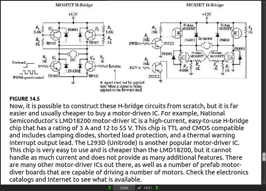
Lastly the modular electronics chapter discusses how you should generally, at least as a hobbyist and during the prototyping phase take advantage of modules and integrated circuits in much the same way that you would use micro controllers rather than build logic circuits from scratch. For example, unless you are building an H-bridge as a learning exercise, you are probably better off buying a module or integrated circuit H-bridge.
Table of Contents
- Chapter 1: Introduction to Electronics
- Chapter 2: Theory
- Chapter 3: Basic Electronic Circuit Components
- Chapter 4: Semiconductors
- Chapter 5: Optoelectronics
- Chapter 6: Sensors
- Chapter 7: Hands-on Electronics
- Chapter 8: Operational Amplifiers
- Chapter 9: Filters
- Chapter 10: Oscillators and Timers
- Chapter 11: Voltage Regulators and Power Supplies
- Chapter 12: Digital Electronics
- Chapter 13: Microcontrollers
- Chapter 14: Motors
- Chapter 15: Audio
- Chapter 16: Modular Electronics
- All page numbers based on epub.
· CHAPTER 1: Introduction to Electronics
· CHAPTER 2: Theory
page 61:
-
Besides the intrinsic elemental semiconductors, such as silicon and germanium, there are hybrid compounds—compounds such as gallium arsenide. Other semiconductors are made by introducing impurities into a silicon lattice. For example, an atom in the chemical group of phosphorous, arsenic, and antimony can replace one of the silicon atoms in a lattice without affecting the lattice itself too much. However, each of these impurities has one more electron in its valence level than the silicon atom has; this extra electron, for which there is no room in the valence band, takes a place in the conduction band and can conduct electricity. A semiconductor with impurities of this sort is called an n-type semiconductor, and the extra electrons are called donor electrons.
-
Atoms of elements in the same chemical group as boron, aluminum, and gallium have one less valence electron than silicon has. If an atom is added to a lattice of silicon as an impurity, there is one less electron than is needed to form a bond that holds the lattice together. This electron must be provided by the electrons of the valence band of the lattice material, and holes are created in this band. These holes act as positive charge carriers. The impurity atoms are called acceptors. A semiconductor with such impurities is called a p-type semiconductor.
page 98:
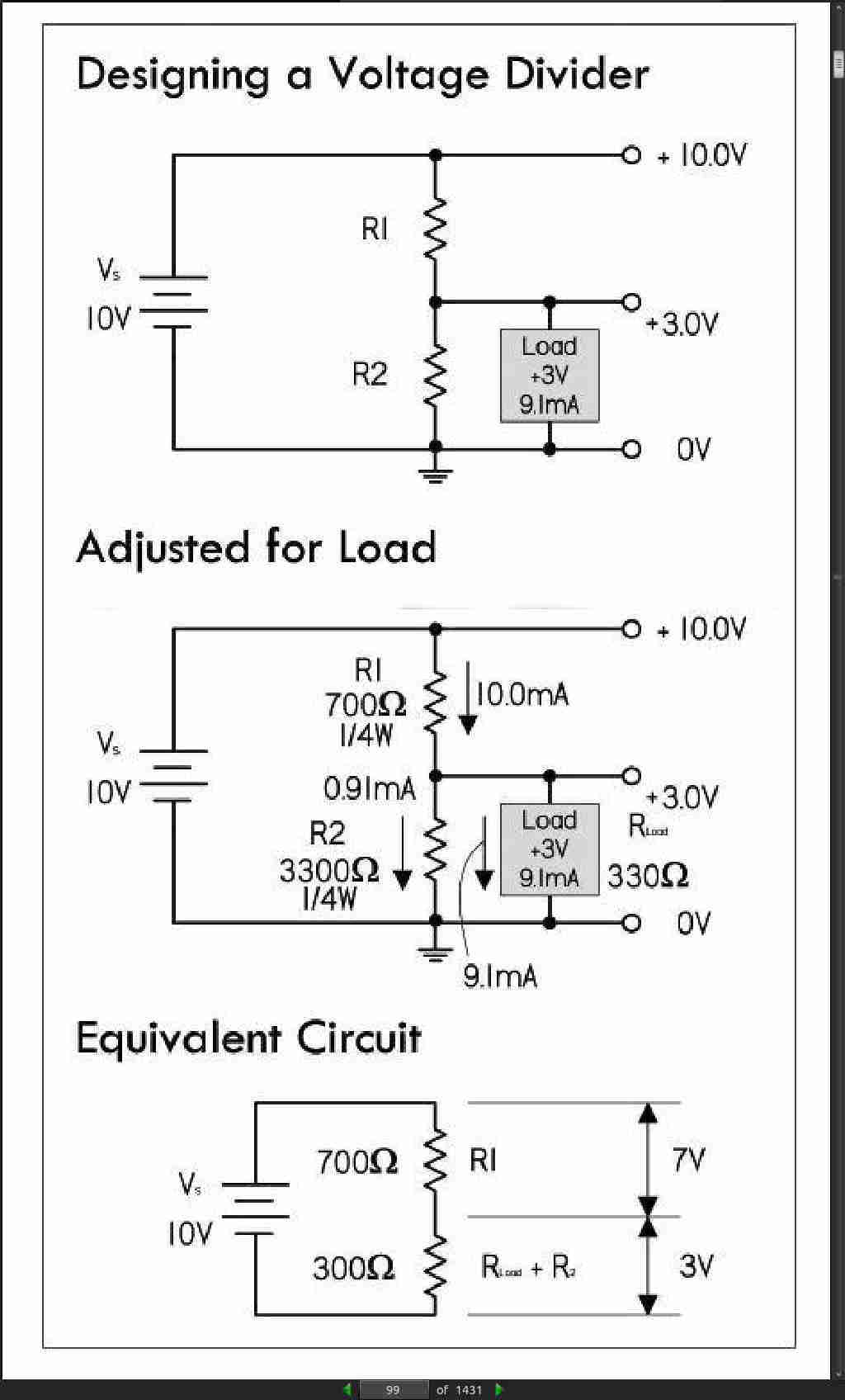
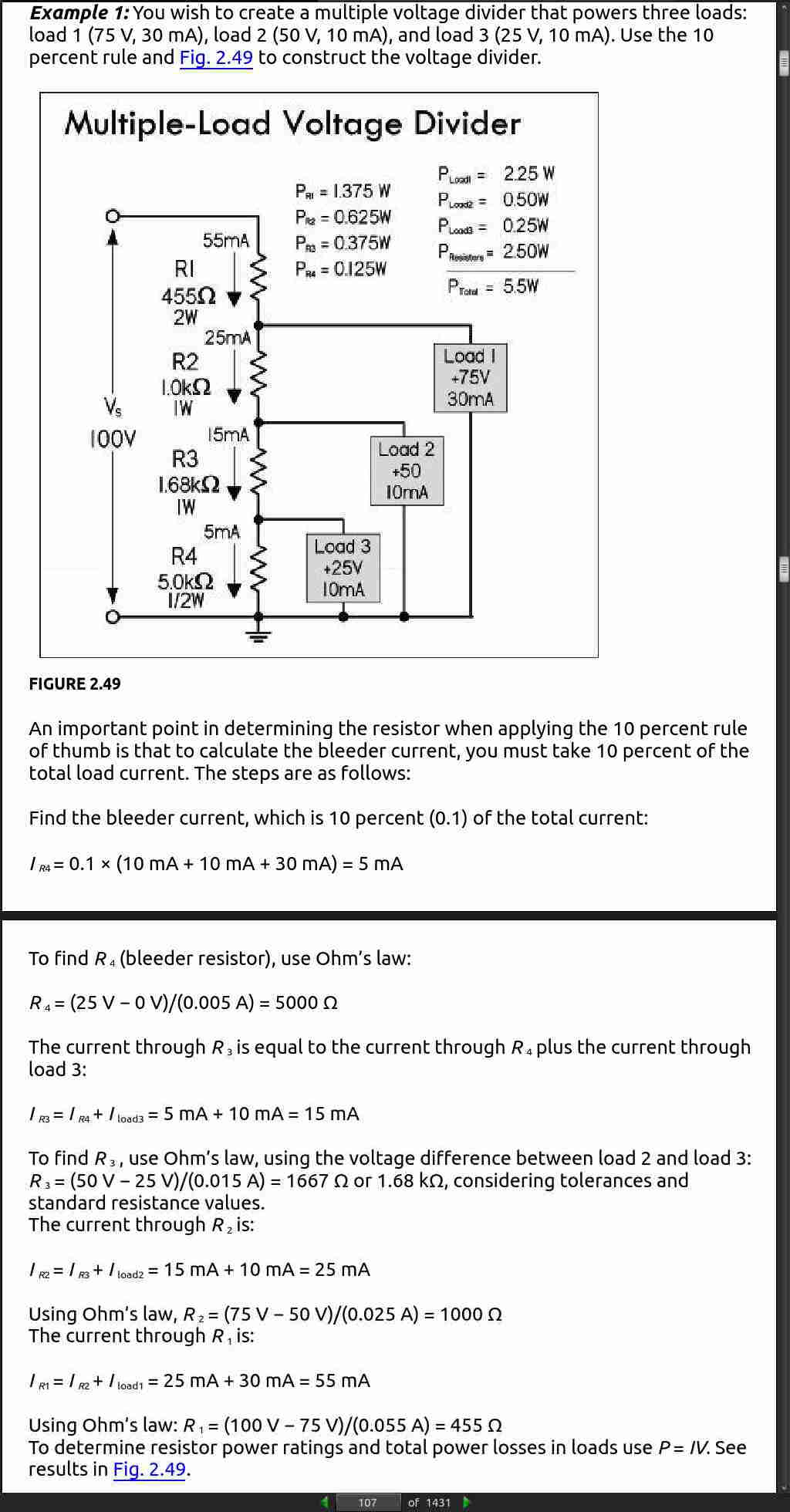
- The 10 Percent Rule: This rule is a standard method for selecting R1 and R2 that takes into account the load and minimizes unnecessary power losses in the divider. The first thing you do is select R2 so that I2 is 10 percent of the desired load current. This resistance and current are called the bleeder resistance and bleeder current.
page 110:
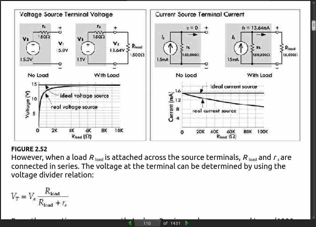
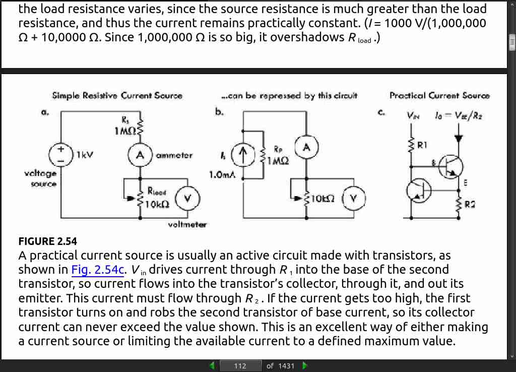
- From the equation, you can see that when R_load is very large compared to r_s , (1000 times greater or more), the effect of r_s is so small that it may be ignored. However, when R load is small or closer to r_s in size, you must take r_s into account when doing your calculations and designing circuits. See the graph in Fig. 2.52. In general, the source resistance for DC power supplies is usually small; however, it can be as high as 600Ω in some cases. For this reason, it’s important to always adjust the power supply voltage with the load connected. In addition, it is a good idea to recheck the power supply voltage as you add or remove components to or from a circuit.
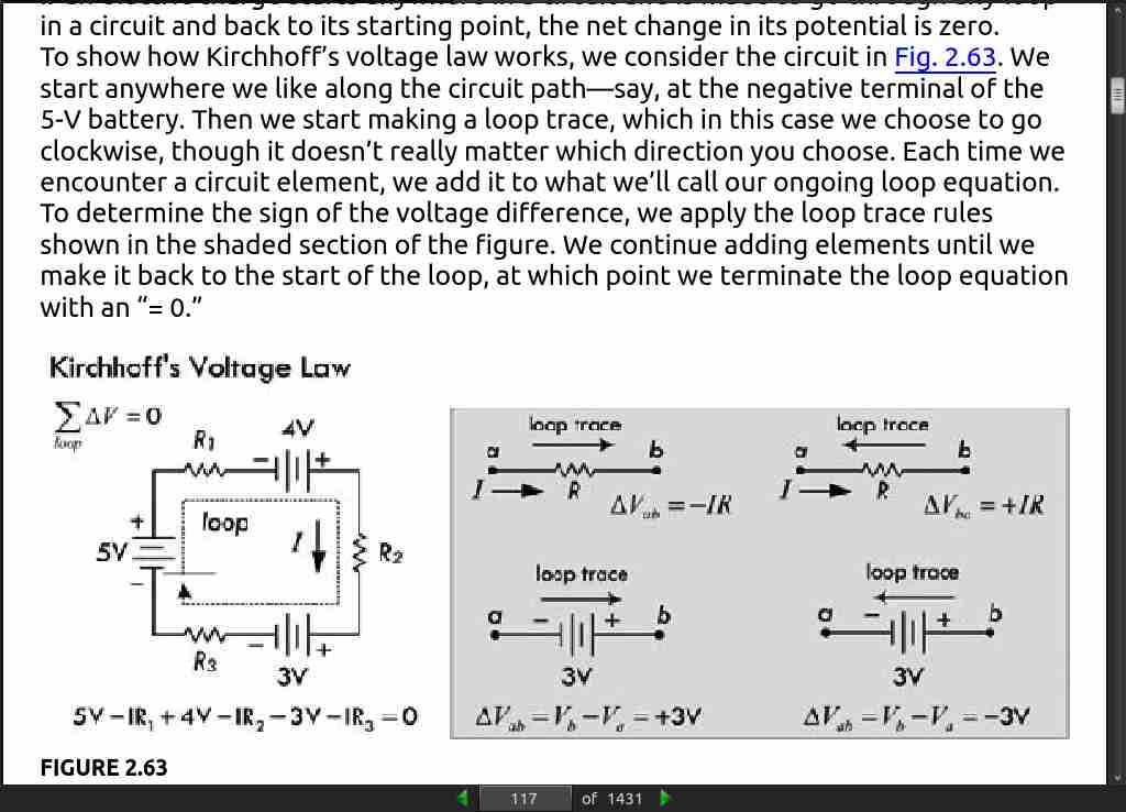
page 123:
- Superposition theorem: The current in a branch of a linear circuit is equal to the sum of the currents produced by each source, with the other sources set equal to zero.
page 142:
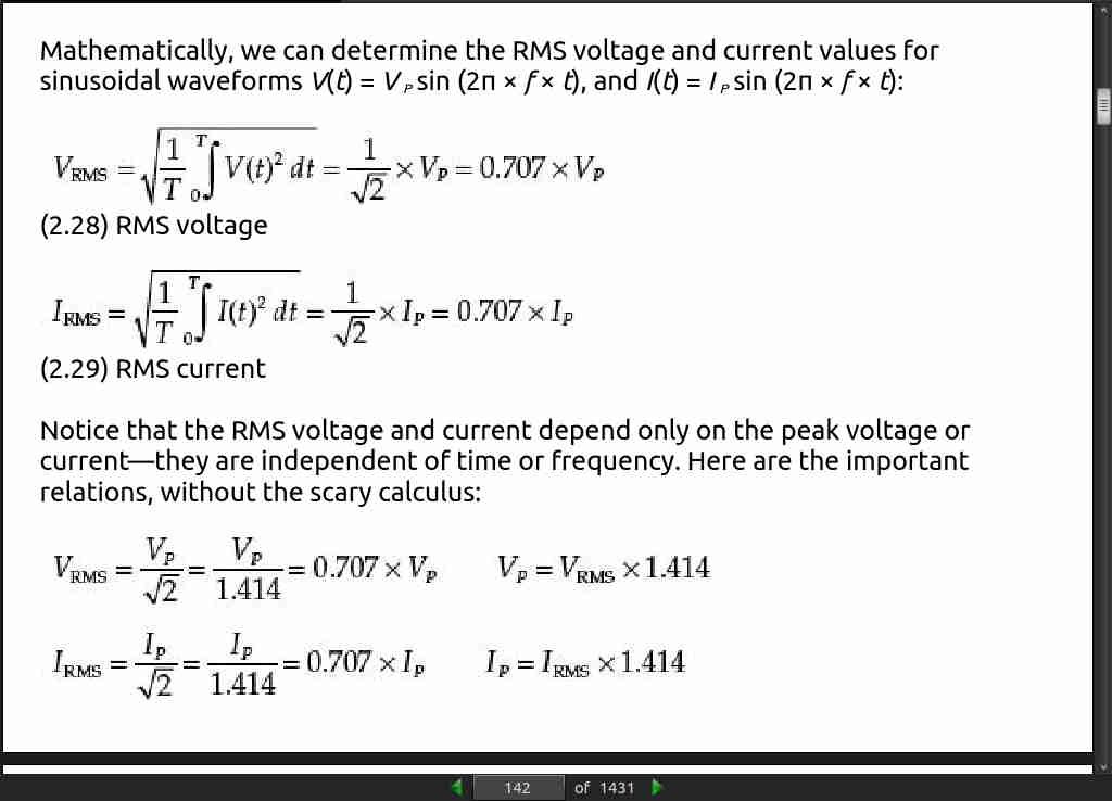
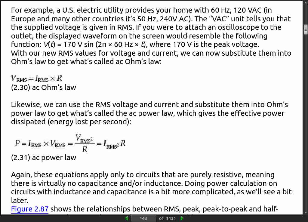
- …RMS or root mean square value, which is found by squaring the instantaneous values of the ac voltage or current, then calculating their mean (i.e., their average), and finally taking the square root of this—which gives the effective value of the ac voltage or current. These effective, or RMS, values don’t average out to zero and are essentially the ac equivalents of dc voltages and currents.
page 147:
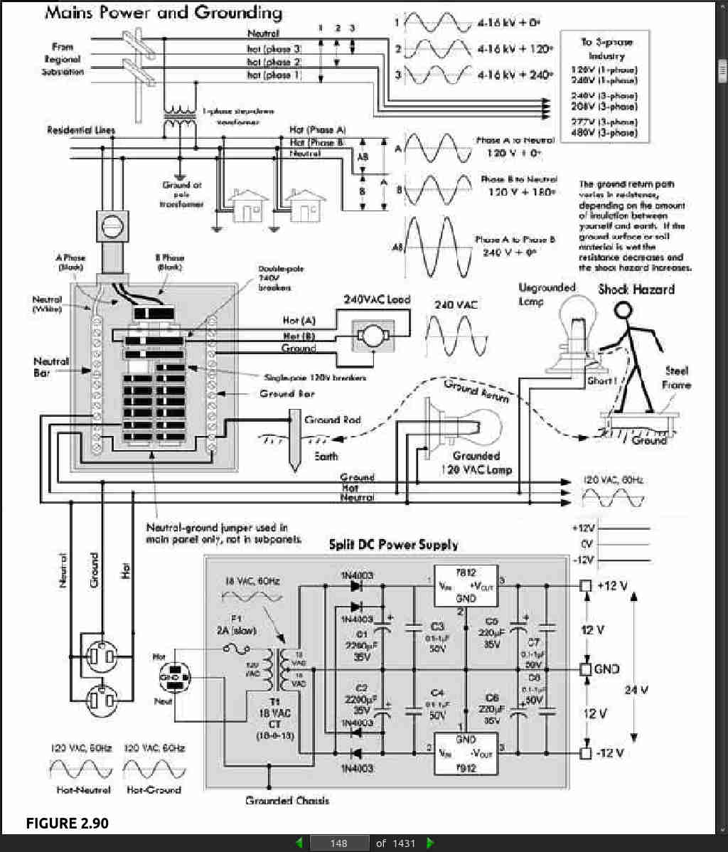
- In the United States, three wires run from the pole transformers (or underground or surface enclosed transformer) to the main service panel at one’s home. One wire is the A-phase wire (usually black in color), another is the B-phase wire (usually black in color), and the third is the neutral wire (white in color). Figure 2.90 shows where these three wires originate from the pole transformer. The voltage between the A-phase and the B-phase wires, or the hot-to-hot voltage, is 240 V, while the voltage between the neutral wire and either the A-phase or the B-phase wire, or the neutral-to-hot voltage, is 120 V. (These voltages are nominal and may vary from region to region, say 117 V instead of 120 V.)
page 149:
At the home, the three wires from the pole/green box transformer are connected through a wattmeter and then enter a main service panel that is grounded to a long copper rod driven into the ground or to the steel in a home’s foundation. The Aphase and B-phase wires that enter the main panel are connected through a main disconnect breaker, while the neutral wire is connected to a terminal referred to as the neutral bar or neutral bus. A ground bar also may be present within the main service panel. The ground bar is connected to the grounding rod or to the foundation’s steel supports. Within the main service panel, the neutral bar and the ground bar are connected together (they act as one). However, within subpanels (service panels that get their power from the main service panel but which are located some distance from the main service panel), the neutral and ground bars are not joined together. Instead, the subpanel’s ground bar receives a ground wire from the main services panel. Often the metal conduit that is used to transport the wires from the main service panel to the subpanel is used as the ground wire. However, for certain critical applications (e.g., computer and life-support systems), the ground wire probably will be included within the conduit. Also, if a subpanel is not located in the same building as the main panel, a new ground rod typically is used to ground the subpanel. Note that different regions within the United States may use different wiring protocols. Therefore, do not assume that what I am telling you is standard practice where you live. Contact your local electrical inspector. Within the main service panel, there are typically two bus bars into which circuit breaker modules are inserted. One of these bus bars is connected to the A-phase wire; the other bus bar is connected to the B-phase wire. To power a group of 120-V loads (e.g., upstairs lights and 120-V outlets), you throw the main breaker to the off position and then insert a single-pole breaker into one of the bus bars. (You can choose either the A-phase bus bar or the B-phase bus bar. The choice of which bus bar you use becomes important only when it comes to balancing the overall load more on that in a moment.) Next, you take a 120-V three-wire cable and connect the cable’s black (hot) wire to the breaker, connect the cable’s white (neutral) wire to the neutral bar, and connect the cable’s ground wire (green or bare) to the ground bar. You then run the cable to where the 120-V loads are located, connect the hot and neutral wires across the load, and fasten the ground wire to the case of the load (typically a ground screw is supplied on an outlet mounting or light figure for this purpose). To power other 120-V loads that use their own breakers, you basically do the same thing you did in the last setup. However, to maximize the capacity of the main panel (or subpanel) to supply as much current as possible without overloading the main circuit breaker in the process, it is important to balance the total load current connected to the A-phase breakers with the total load current connected to the B-phase breakers. This is referred to as “balancing the load.” Now, if you want to supply power to 240-V appliances (ovens, washers, etc.), you insert a double-pole breaker between the A-phase and B-phase bus bars in the main (or subpanel). Next, you take a 240-V three-wire cable and attach one of its hot wires to the A-phase terminal of the breaker and attach its other hot wire to the B phase terminal of the breaker. The ground wire (green or bare) is connected to the ground bar. You then run the cable to where the 240-V loads are located and attachthe wires to the corresponding terminals of the load (typically within a 240-V outlet). Also, 120-V/240-V appliances are wired in a similar manner, except you use a four-wire cable that contains an additional neutral (white) wire that is joined at the neutral bar within the main panel (or subpanel).
page 188:
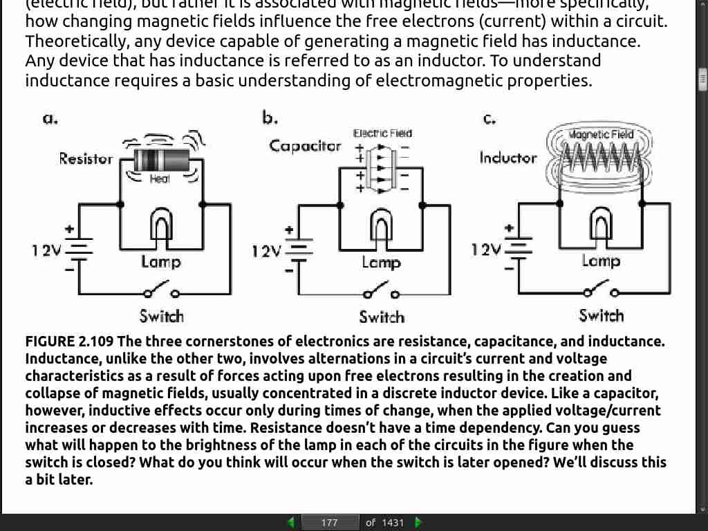
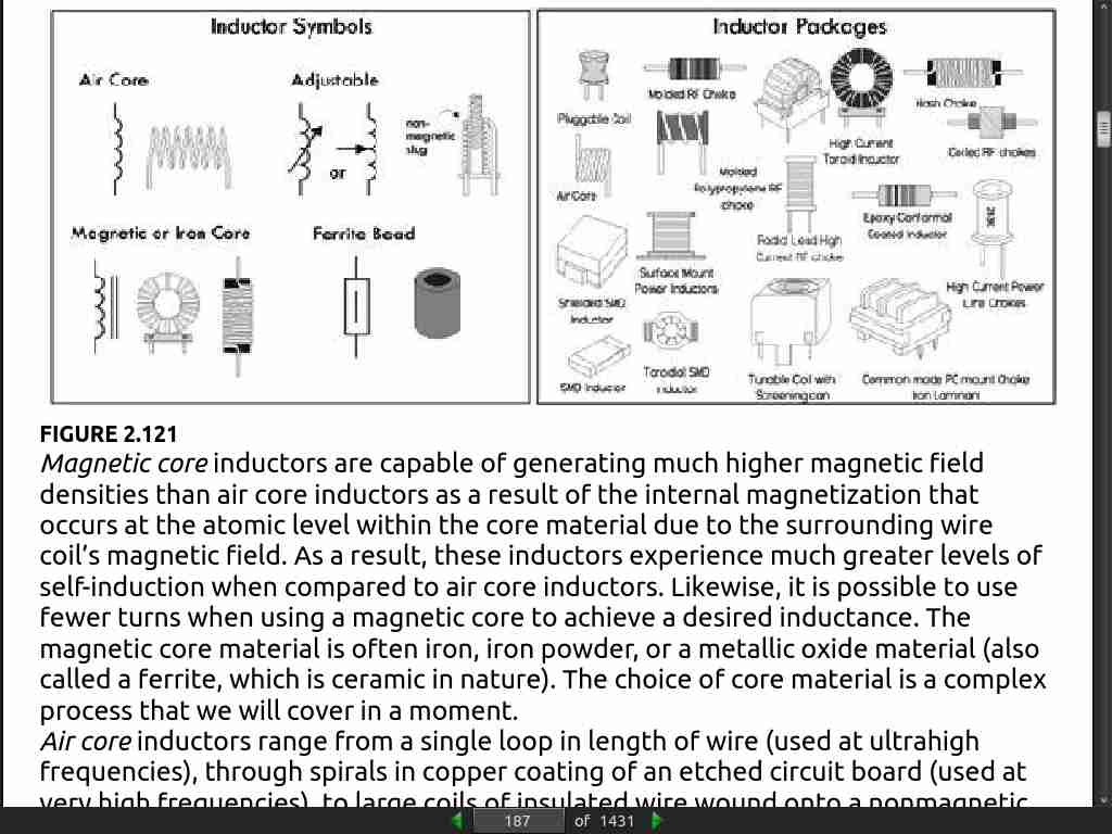
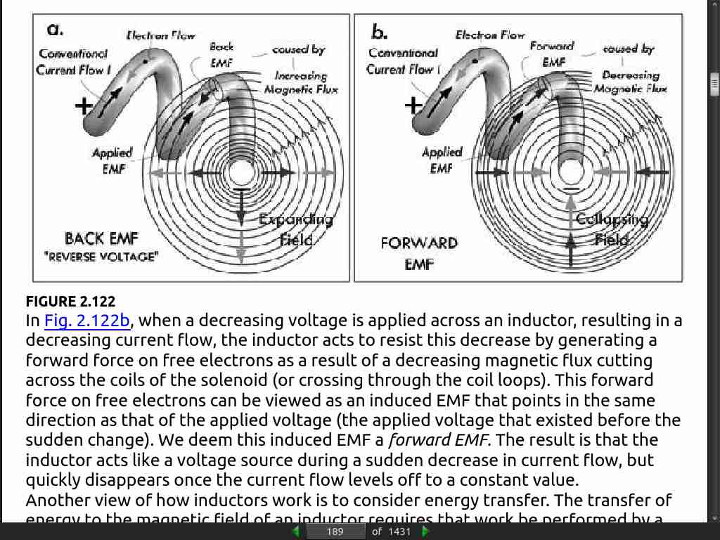
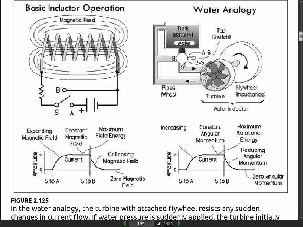
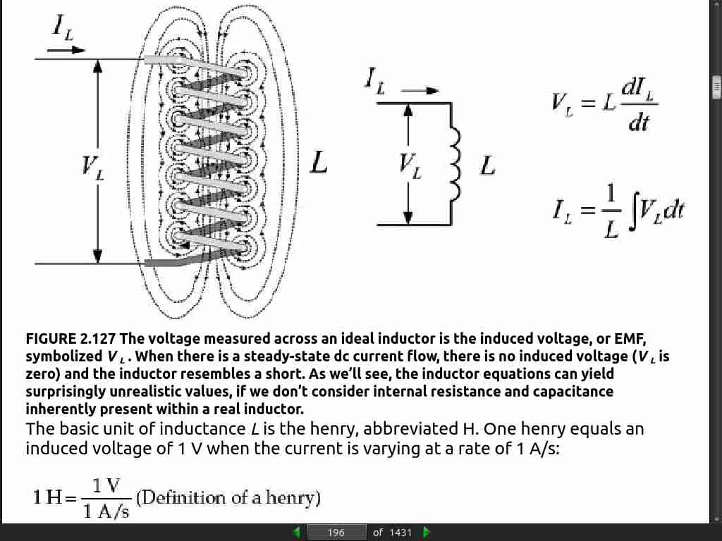
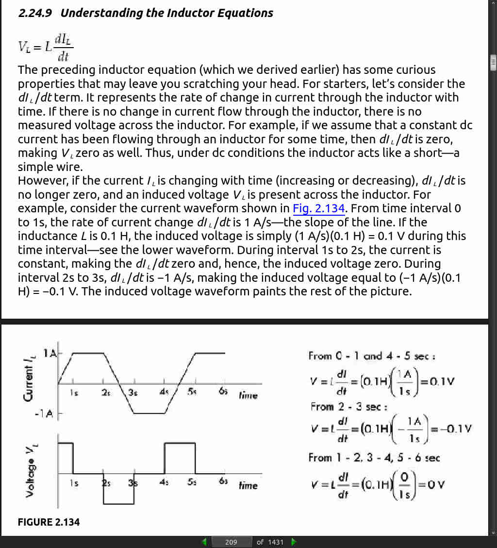
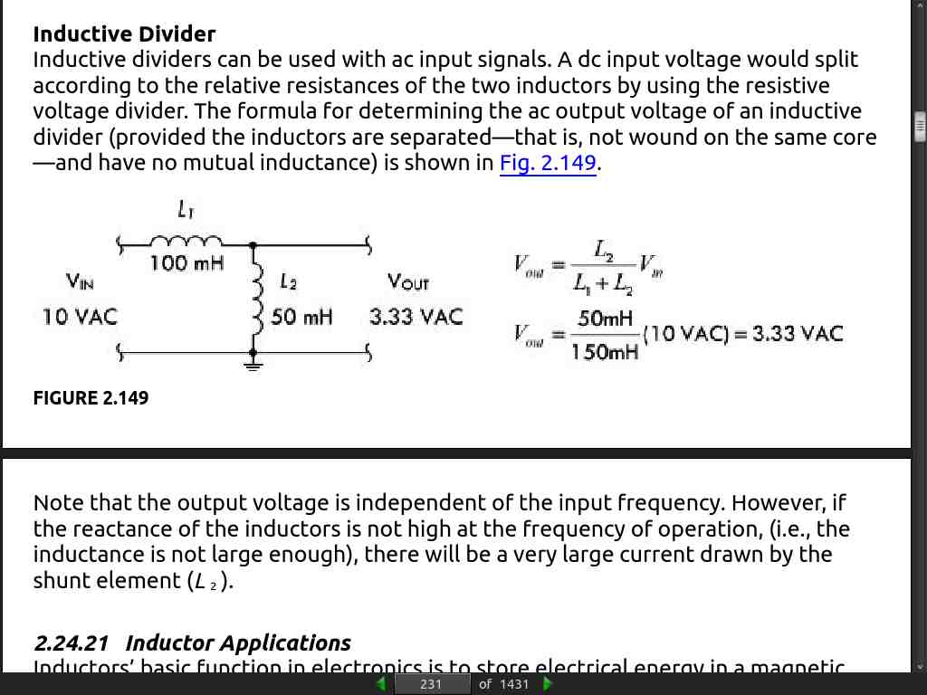
- An inductor acts like a time-varying current-sensitive resistance. It only “resists” during changes in current; otherwise (under steady-state dc conditions), it passes current as if it were a wire. When the applied voltage increases, it acts like a time dependent resistor whose resistance is greatest during times of rapid increase in current. On the other hand, when the applied voltage decreases, the inductor acts like a time-dependent voltage source (or negative resistance) attempting to keep current flowing.
page 283:
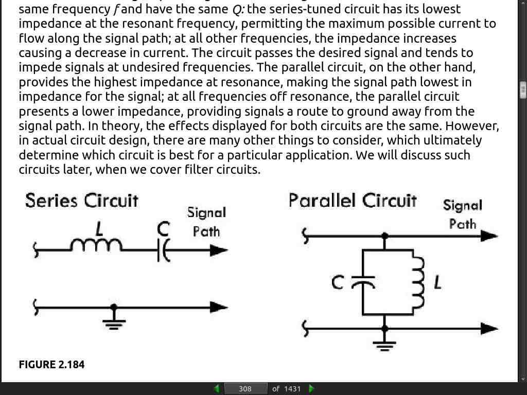
- resonant frequency f0 = 1/(2pisqrt(LC))
page 285:
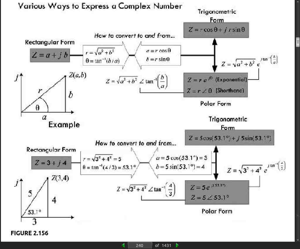
- Note that we got the phase angle by assuming that the arc tangent of anything divided by 0 is 90°.
page 286:
- Note that we got the phase angle by assuming that the negative arc tangent of anything over zero is −90°.
page 315:
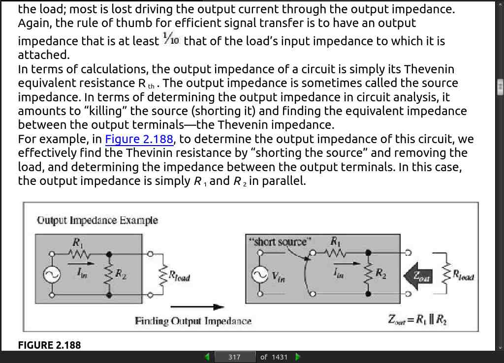
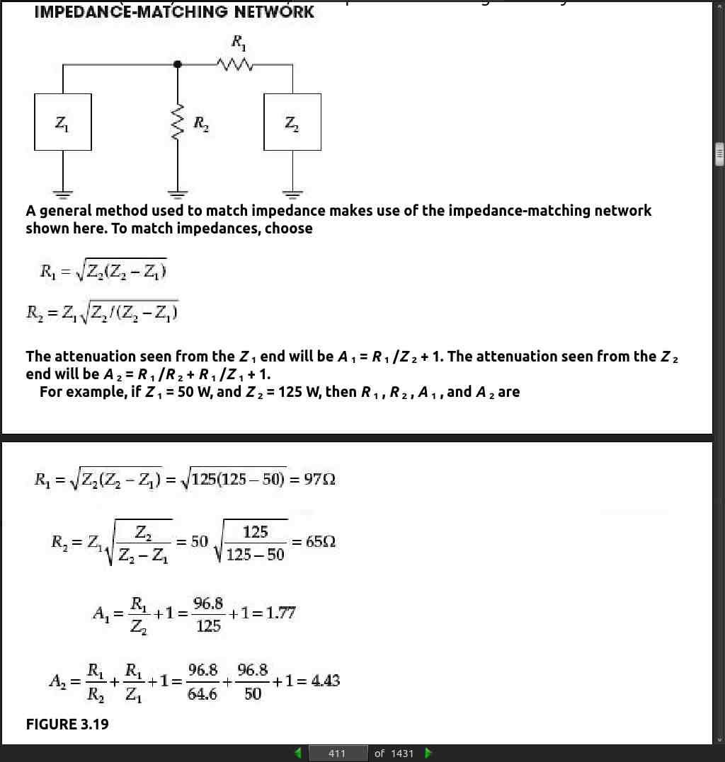
- As a general rule of thumb, in terms of transmitting a signal, the input impedance of a device should be greater than the output impedance of the circuit supplying the signal to the input. Generally, the value should be 10 times as great to ensure that the input will not overload the source of the signal and reduce the strength by a substantial amount.
page 317:
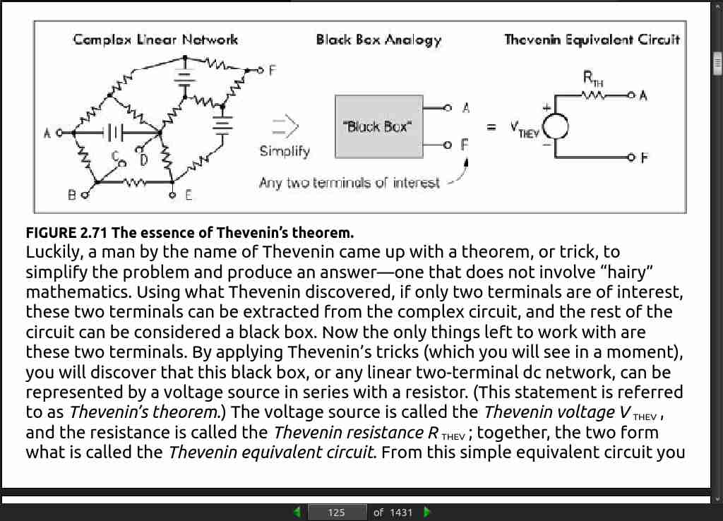
- the output impedance of a circuit is simply its Thevenin equivalent resistance R_th.
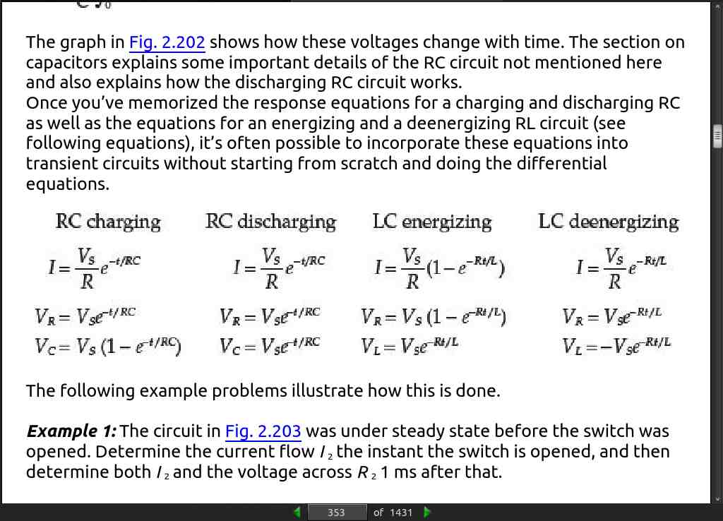
page 356:
-
Here are some important things to notice during a forced response in regard to resistors, capacitors, and inductors:
-
Resistor: Under a forced response, a voltage is instantly placed across a resistor and a current immediately flows. There is no delay in voltage or current response (ideally).
-
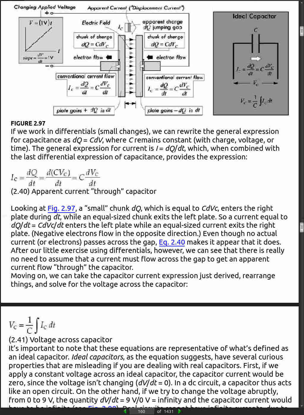
Capacitor: Under a forced response, the voltage across a capacitor cannot change instantly, so at the instant a transition occurs it acts like an open circuit or constant voltage source. The voltage at instant t=0− or t=0+ is a constant—the voltage that was present before the event. Also, at the instant t=0− or t=0+ the current is zero, since no time transpires for charge to accumulate. However, after t=0+ , the capacitor voltage and current have a natural response that is a function of time.
-
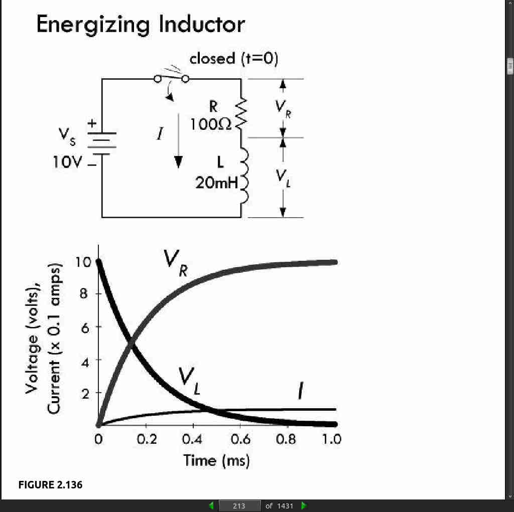
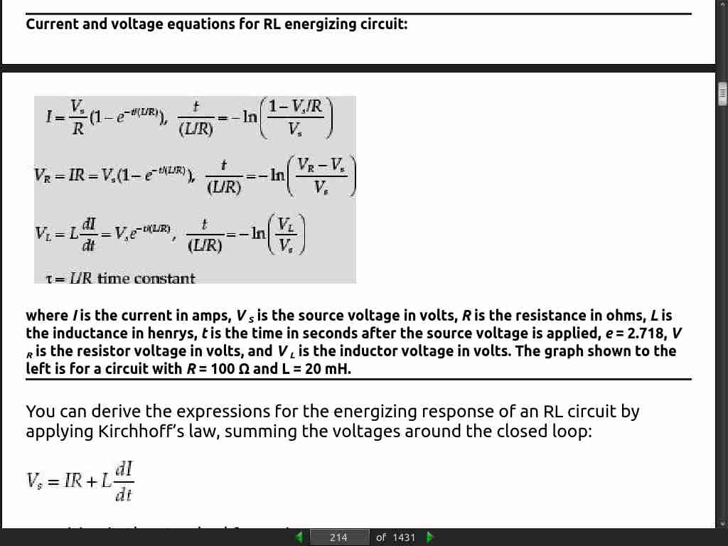
Inductor: Under a forced response, an inductor voltage cannot change instantaneously, so it acts like a short, meaning there is no voltage across it at t=0− or t=0+ . The current, however, at t=0− or t=0+ will be a constant—the value of the current prior to the transient event. However, after t=0+ , the inductor voltage and current have a natural response that is a function of time.
page 376:
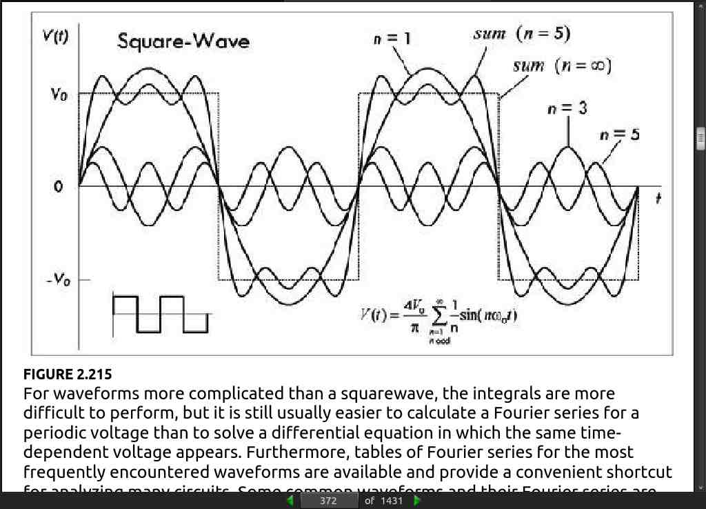
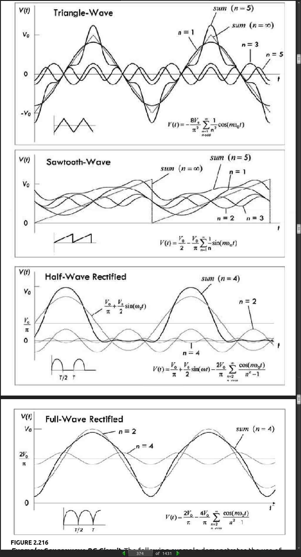
- Nonperiodic voltages and currents can also be represented as a superposition of sine waves as with the Fourier series. However, instead of a summation over a set of discrete, harmonically related frequencies, the waveforms have a continuous spectrum of frequencies. It is possible to think of a nonperiodic function as a periodic function with an infinite period.
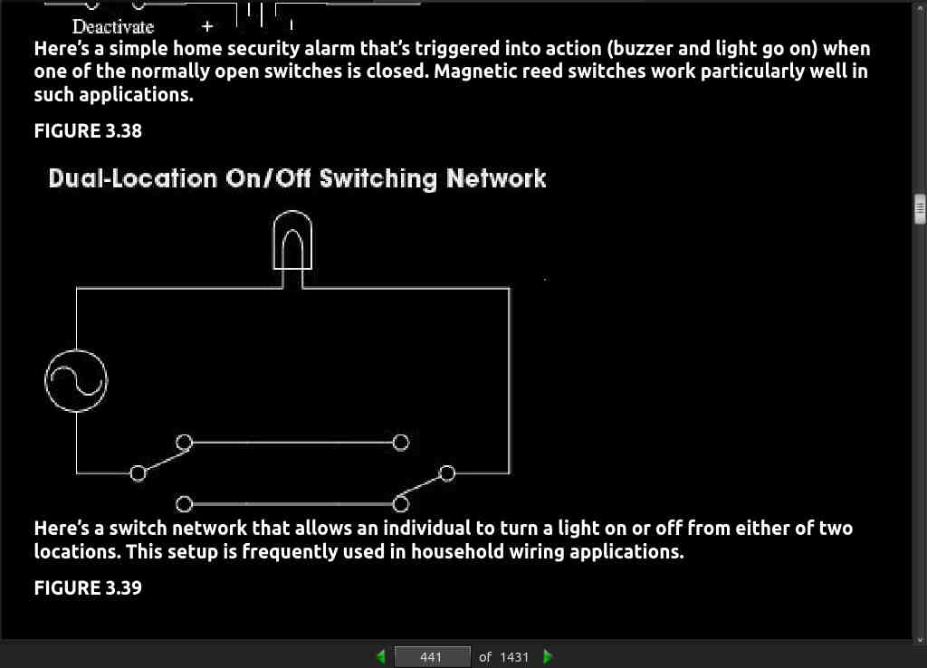
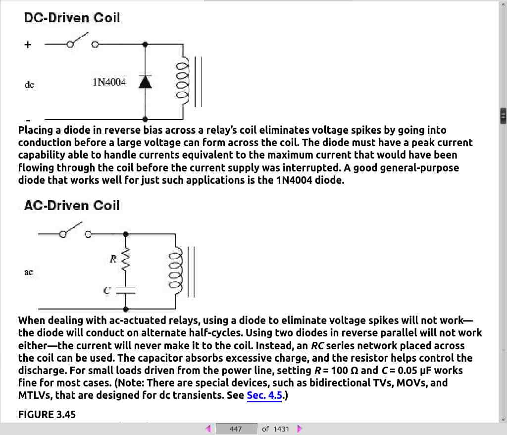
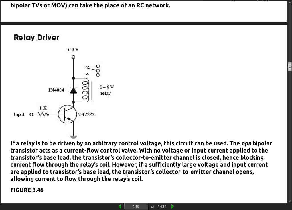
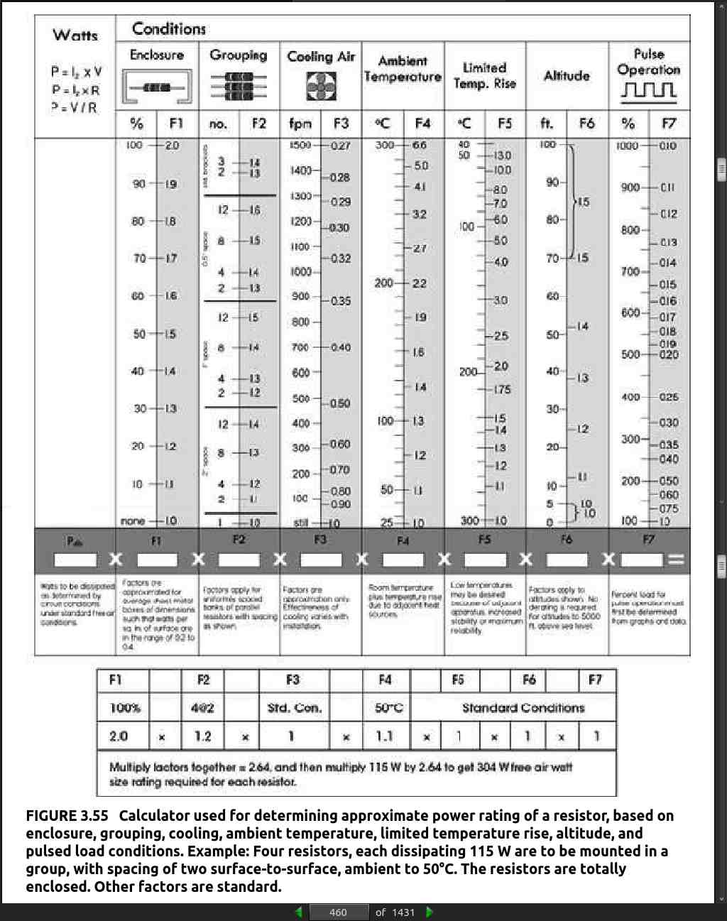
· CHAPTER 3: Basic Electronic Circuit Components
page 479:
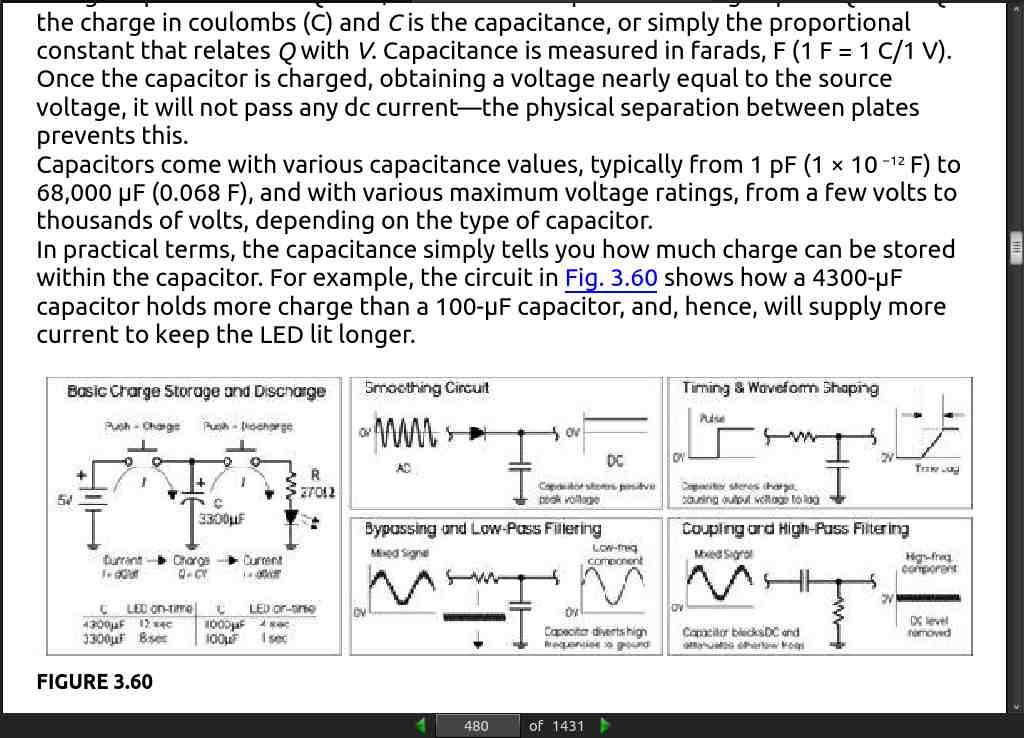
- a capacitor placed in parallel with a signal path (i.e., to ground) has an effect opposite that of the coupling capacitor. Instead, it acts as a decoupling capacitor, allowing dc to continue along the path, while diverting high-frequency signal components to ground—the capacitor acts as a low-impedance path to ground. A similar effect, known as bypassing, is used when a capacitor is placed across a particular circuit element to divert unwanted frequencies around it. Decoupling and bypassing become fundamental when removing unwanted random high-frequency ripple and other undesired alterations within a supply voltage (or voltage-critical location) caused by random noise, or sudden current demands generated by accompanying circuit elements. Without decoupling and bypassing, many sensitive circuits, especially those incorporating digital logic ICs, have a tendency to misbehave.
page 485:
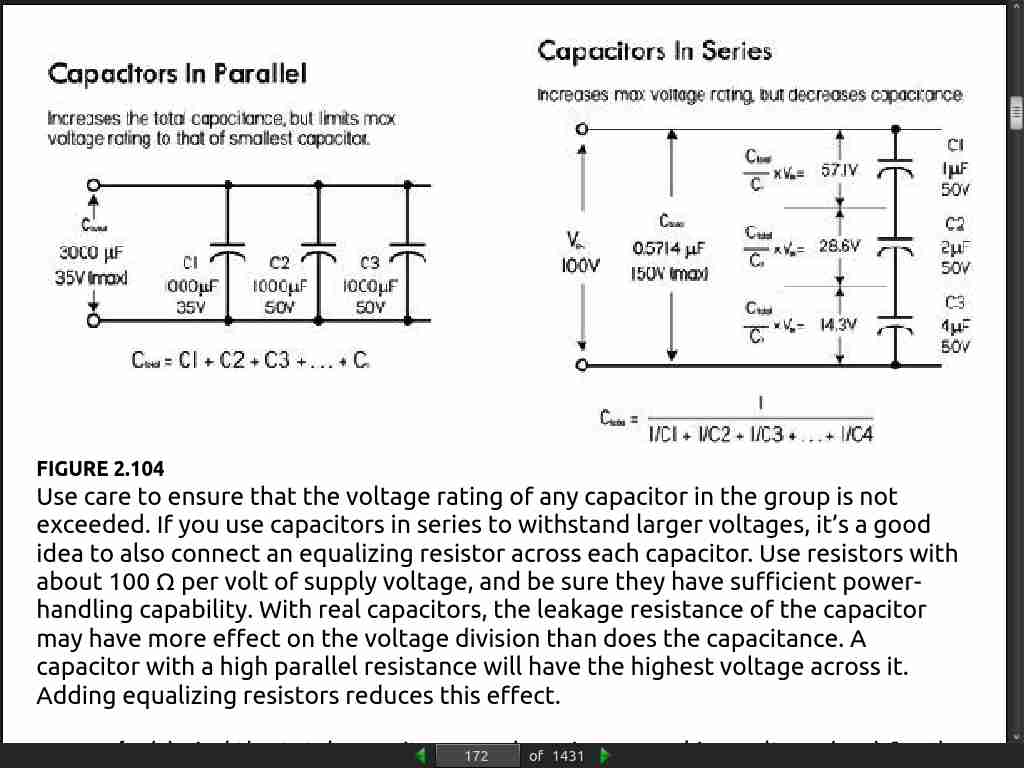
- [capacitor] For use with other ac signals, the peak value of ac voltage should not exceed the dc working voltage, unless otherwise specified in component ratings. In other words, the RMS value of ac should be 0.707 times the DCWV [DC Working Voltage] value or lower.
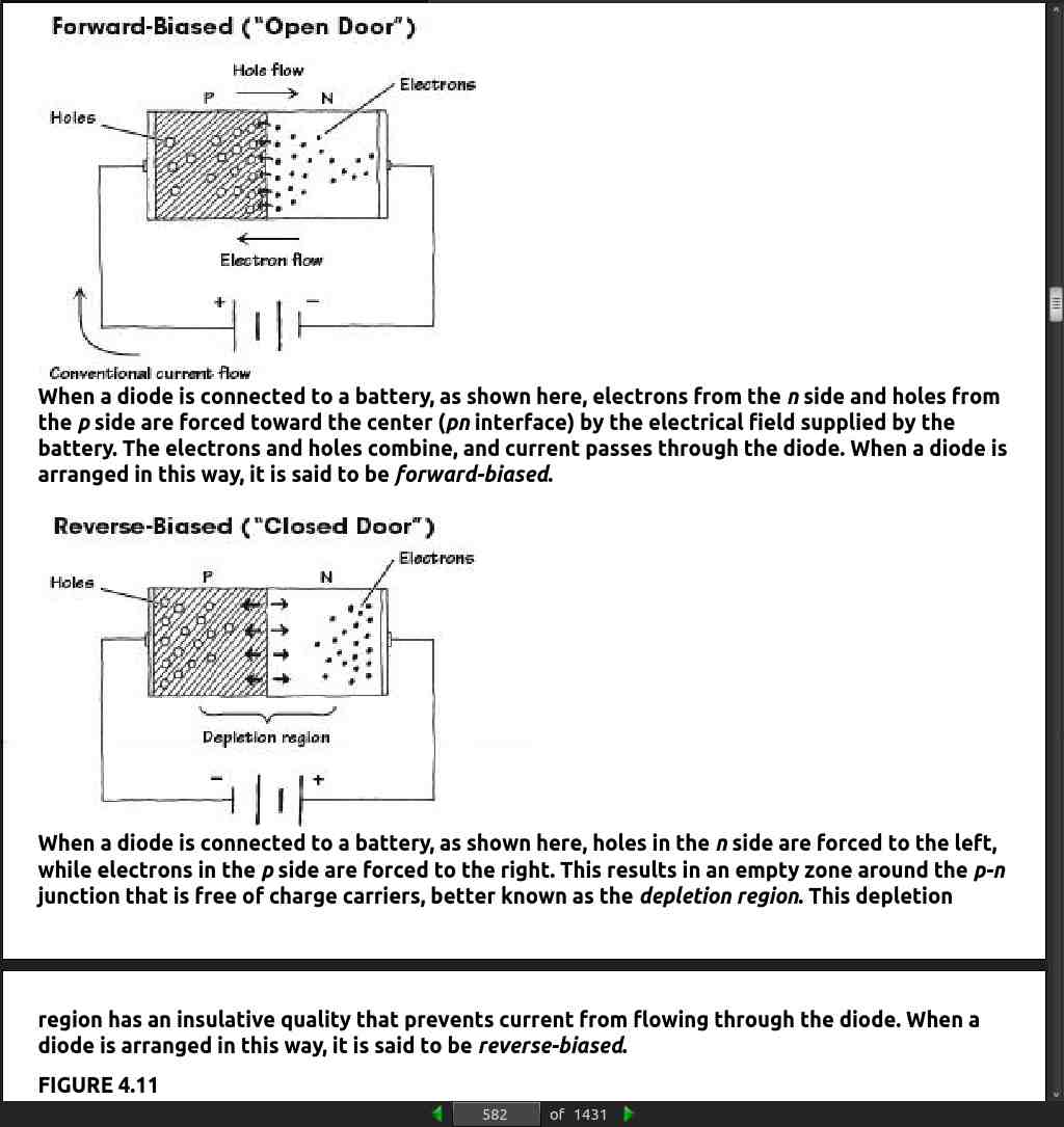
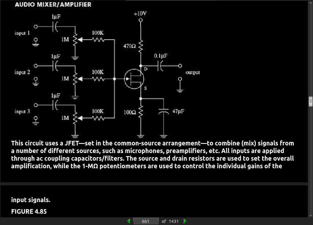
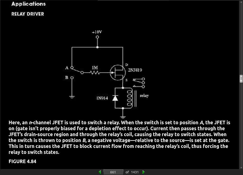
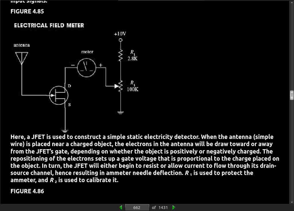
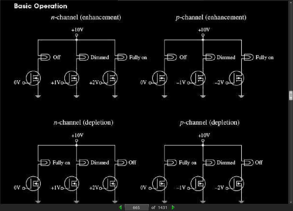
· CHAPTER 4: Semiconductors
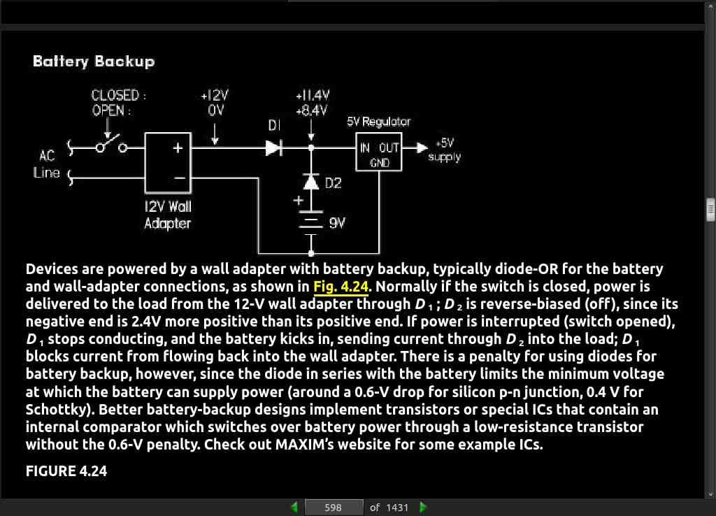
page 656:
- JFET followers are often used as input stages to amplifiers, test instruments, or other equipment that is connected to sources with high source impedance.
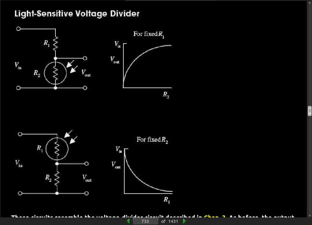
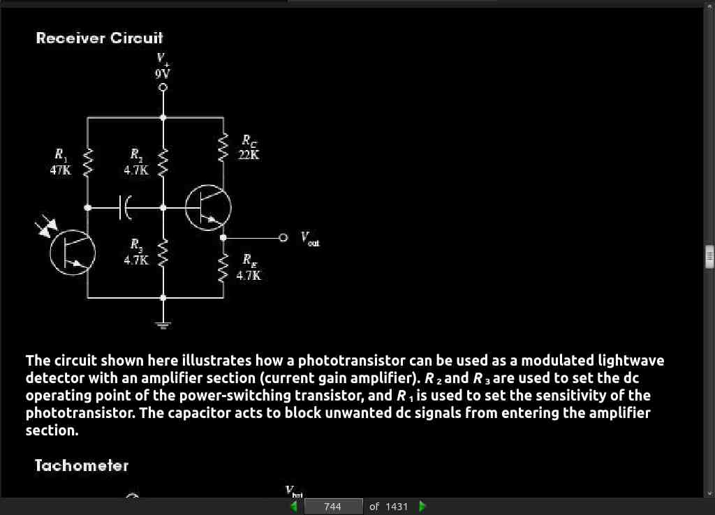
· CHAPTER 5: Optoelectronics
page 747:
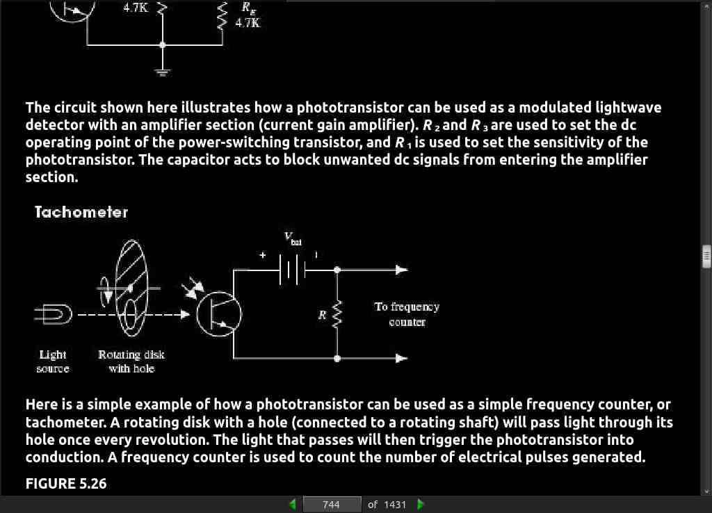
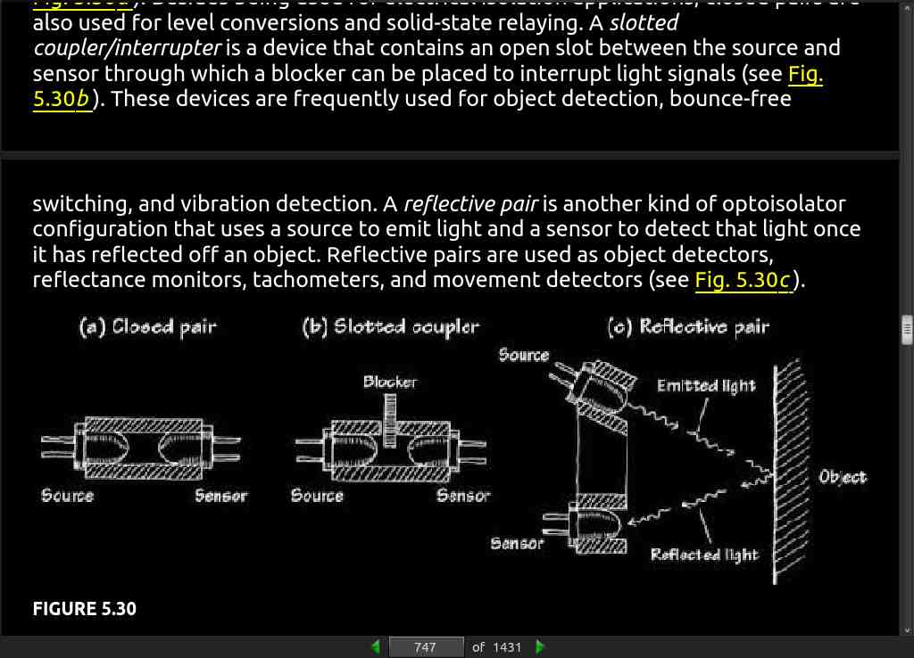
- A slotted coupler/interrupter is a device that contains an open slot between the source and sensor through which a blocker can be placed to interrupt light signals (see Fig. 5.30b). These devices are frequently used for object detection, bounce-freeswitching, and vibration detection. A reflective pair is another kind of optoisolator configuration that uses a source to emit light and a sensor to detect that light once it has reflected off an object. Reflective pairs are used as object detectors, reflectance monitors, tachometers, and movement detectors (see Fig. 5.30c).
· CHAPTER 6: Sensors
page 759:
- The most commonly used metals for a thermocouple are the alloys chromel (90 percent nickel and 10 percent chromium) and alumel (95 percent nickel, 2 percent manganese, 2 percent aluminum, and 1 percent silicon). A thermocouple made with these materials will typically be able to measure temperatures over the range -200°C to +1350°C. The sensitivity is 41 μV / °C for these metals.
· CHAPTER 7: Hands-on Electronics

· CHAPTER 8: Operational Amplifiers
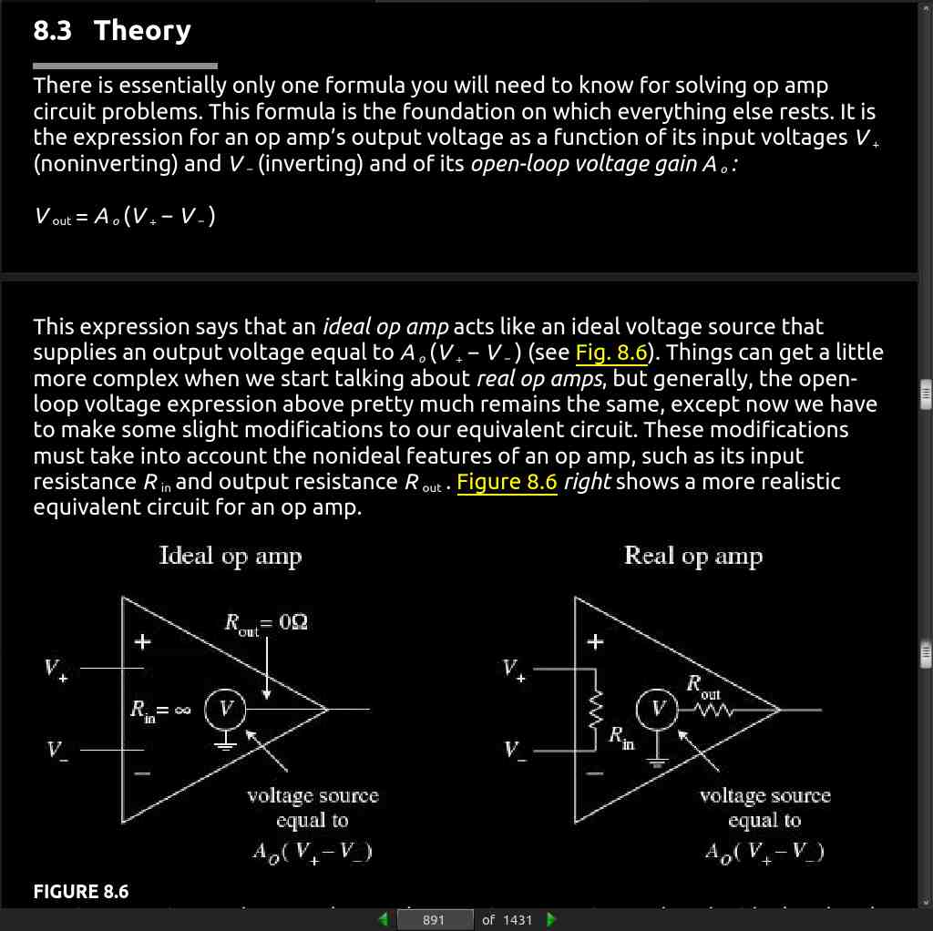
page 891:
-
Rule 1: For an ideal op amp, the open-loop voltage gain is infinite (A_o = ∞). For a real op amp, the gain is a finite value, typically between 10^4 to 10^6.
-
Rule 2: For an ideal op amp, the input impedance is infinite (R in = ∞). For a real op amp, the input impedance is finite, typically between 10^6 (e.g., typical bipolar op amp) to 10^12 Ω (e.g., typical JFET op amp). The output impedance for an ideal op amp is zero (R out = 0). For a real op amp, R out is typically between 10 to 1000 Ω.
-
Rule 3: The input terminals of an ideal op amp draw no current. Practically speaking, this is true for a real op amp as well—the actual amount of input current is usually (but not always) insignificantly small, typically within the picoamps (e.g., typical JFET op amp) to nanoamps (e.g., typical bipolar op amp) range.
page 893:
Rule 4: Whenever an op amp senses a voltage difference between its inverting and noninverting inputs, it responds by feeding back as much current/voltage through the feedback network as is necessary to keep this difference equal to zero (V_+ − V_− = 0). This rule only applies for negative feedback.
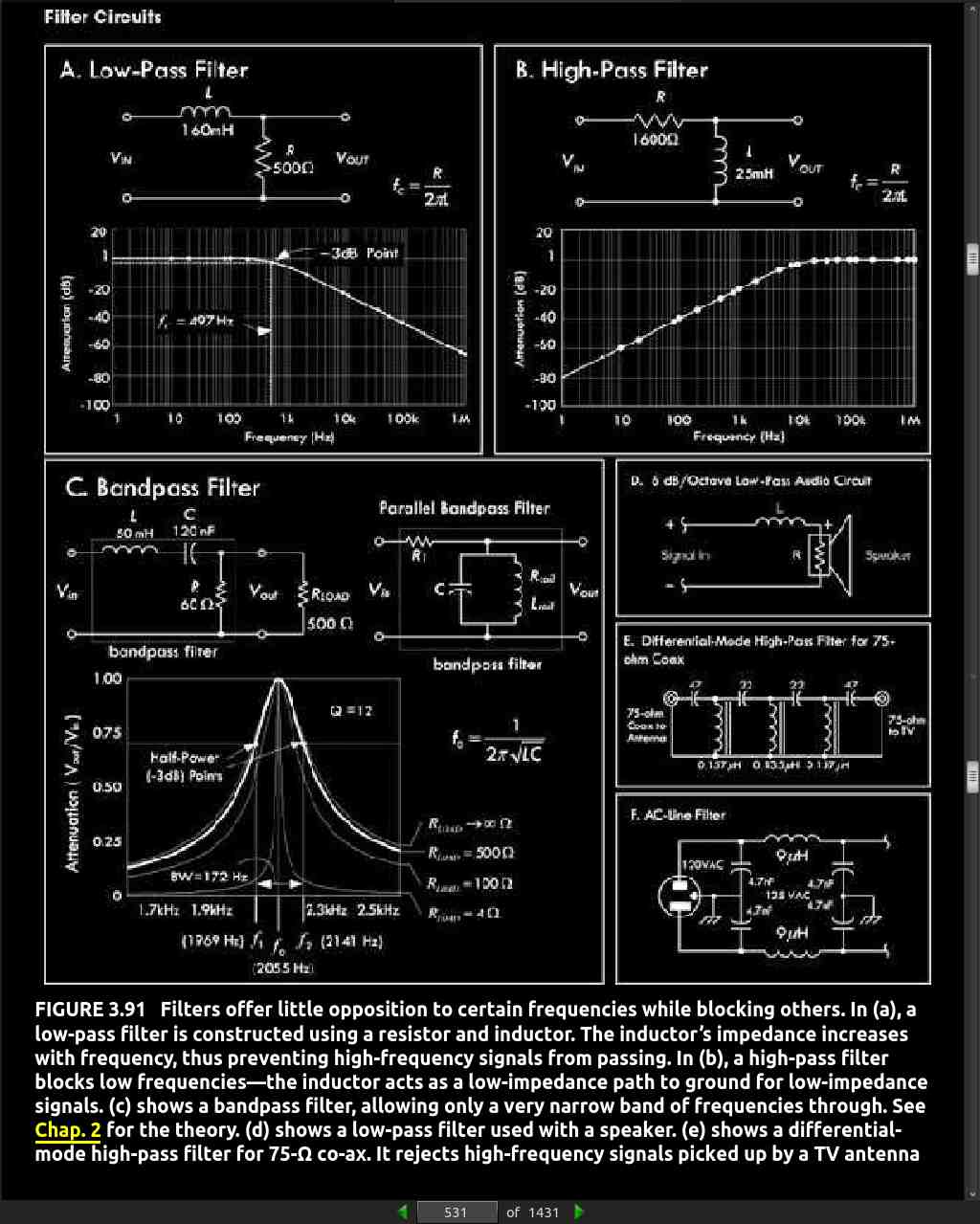
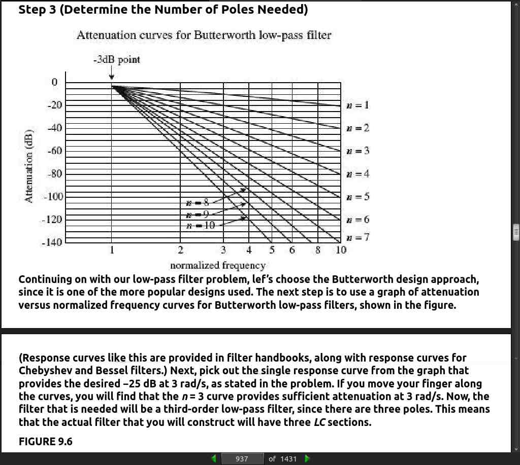
· CHAPTER 9: Filters
page 932:
-
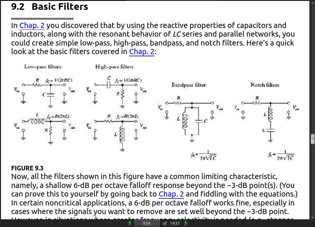
Passive filters are designed using passive elements (e.g., resistors, capacitors, and inductors) and are most responsive to frequencies between around 100 Hz and 300 MHz.
-
Active filters are capable of handling very low frequency signals (approaching 0 Hz), and they can provide voltage gain if needed (unlike passive filters).
-
Above around 100 kHz or so, active filters can become unreliable (a result of the op amp’s bandwidth and slew-rate requirements).
-
At radiofrequencies, it is best to use a passive filter.
-
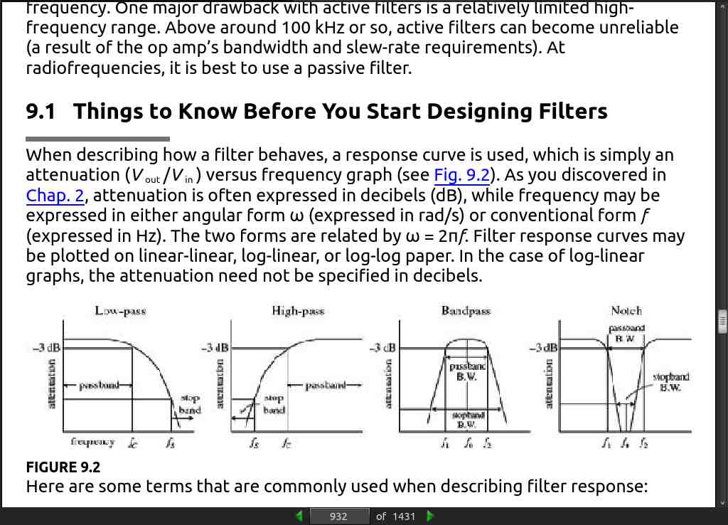
When describing how a filter behaves, a response curve is used, which is simply an attenuation (Vout/Vin ) versus frequency graph (see Fig. 9.2). As you discovered in Chap. 2, attenuation is often expressed in decibels (dB), while frequency may be expressed in either angular form ω (expressed in rad/s) or conventional form f (expressed in Hz). The two forms are related by ω = 2πf.
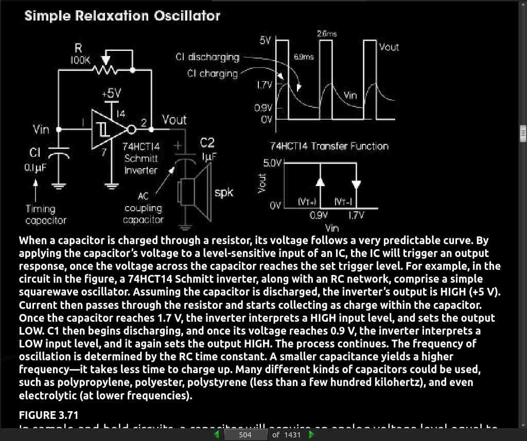
· CHAPTER 10: Oscillators and Timers
page 973:
- 10.2 The 555 Timer IC
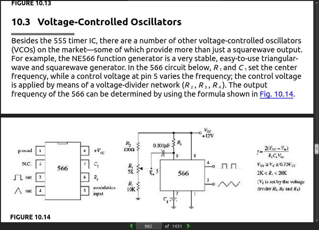
page 982:
-
Other VCOs (voltage controlled oscillators), such as the 8038 and the XR2206, can create a trio of output waveforms, including a sine wave (approximation of one, at any rate), a square wave, and triangular wave.
-
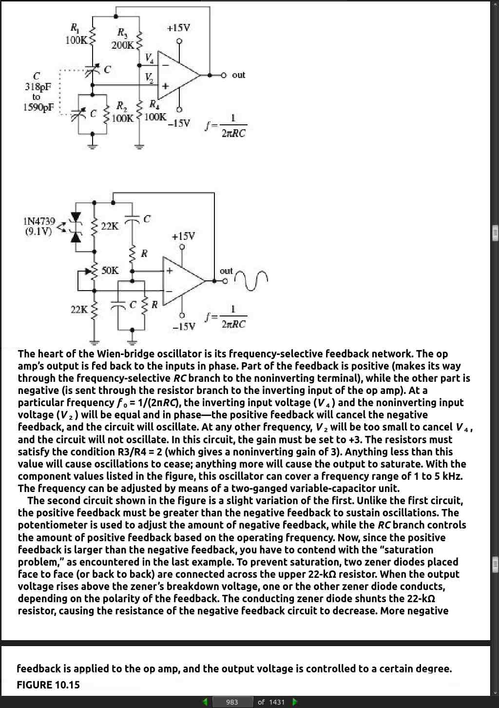
A popular RC-type circuit used to generate low-distortion sinusoidal waves at low to moderate frequencies is the Wien-bridge oscillator.
page 984:
-
When it comes to generating high-frequency sinusoidal waves, commonly used in radiofrequency applications, the most common approach is to use an LC oscillator.
-
can reach frequencies up to around 500 MHz. However, it is important to note that at low frequencies (e.g., audio range), LC oscillators become highly unwieldy.
page 993:
-
There are a number of ICs available that can make designing crystal oscillators a breeze. Some of these ICs, such as the 74S124 TTL VCO (squarewave generator), can be programmed by an external crystal to output a waveform whose frequency is determined by the crystal’s resonant frequency. The MC12060 VCO, unlike the 74S124, outputs a pair of sine waves.
-
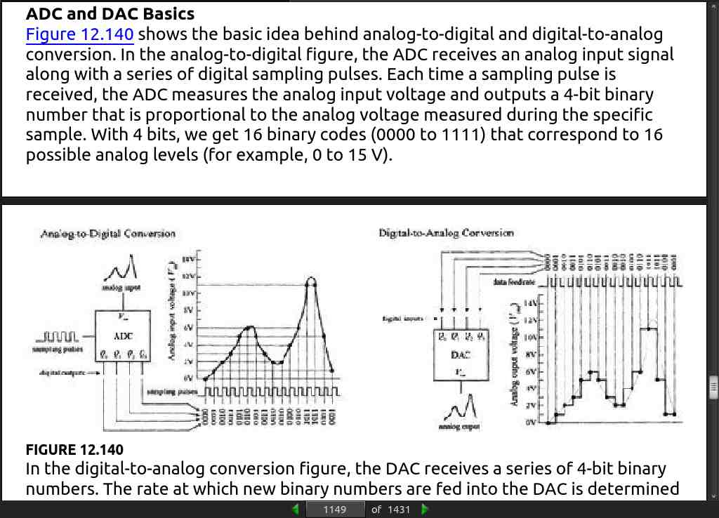
In Chap. 13, we will also see how a microcontroller can be used to generate a waveform using a digital-to-analog convertor. The basic technique is to store the waveform in memory and then play it through the digital-to-analog converter. In the case where just a squarewave is required, a simple 8-pin microcontroller with a built-in clock can be an effective alternative to a 555 timer, requiring fewer external components.
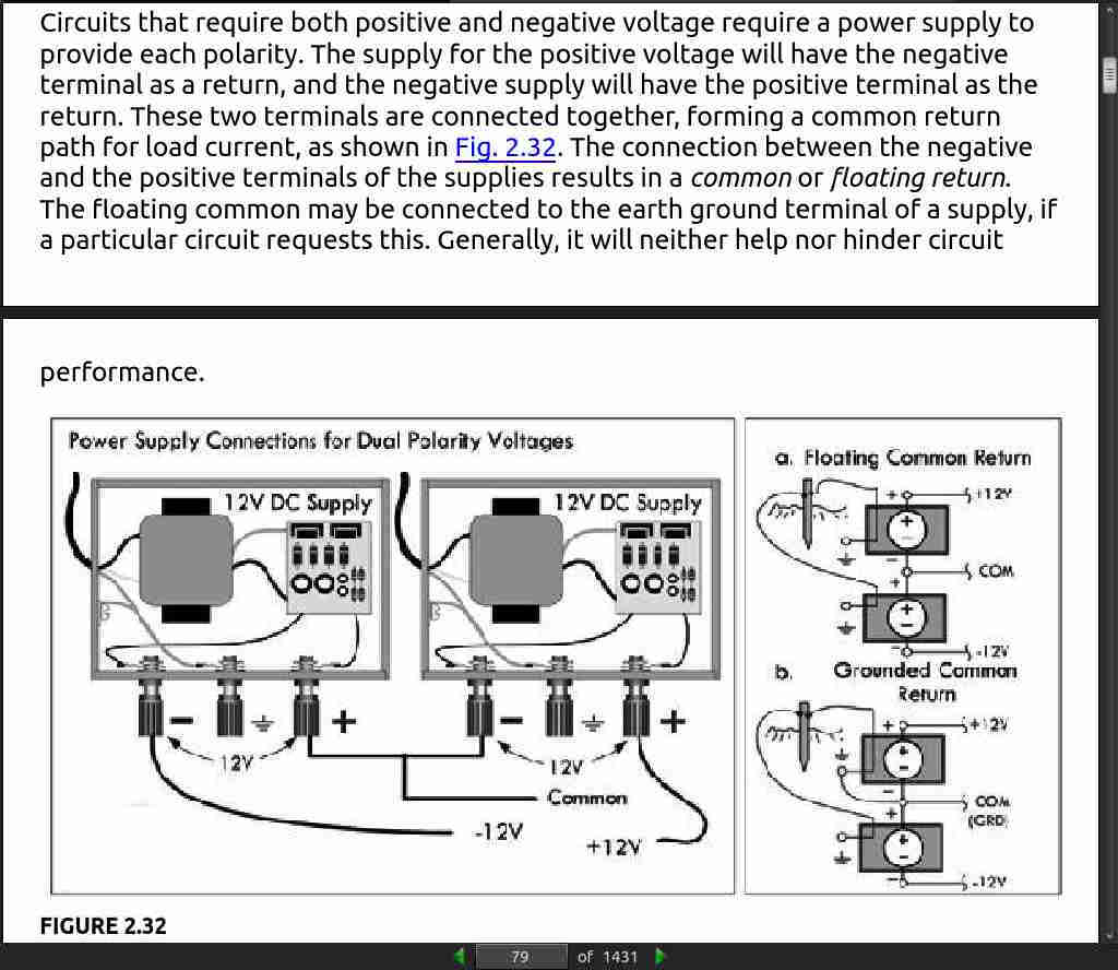
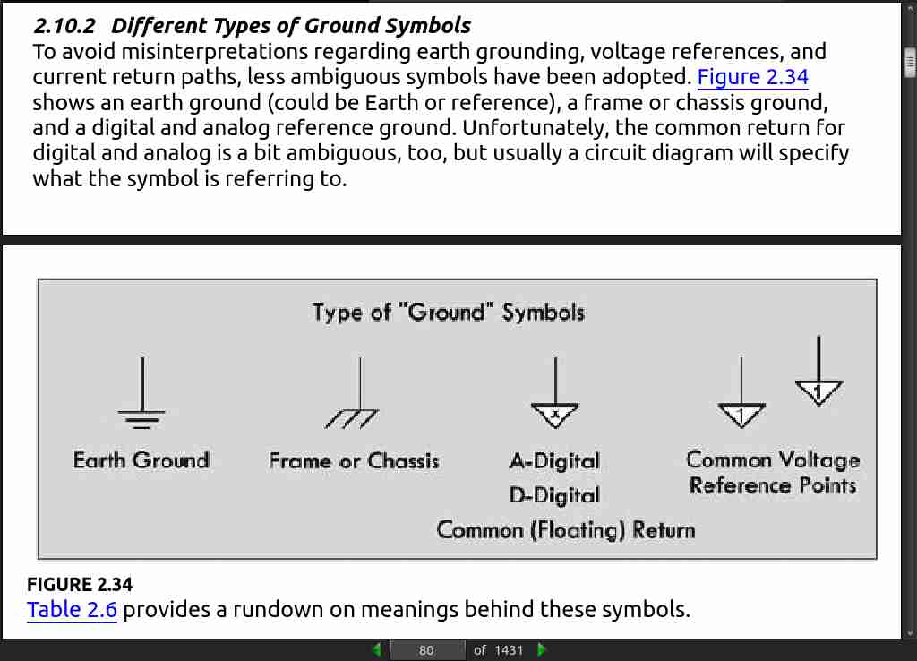
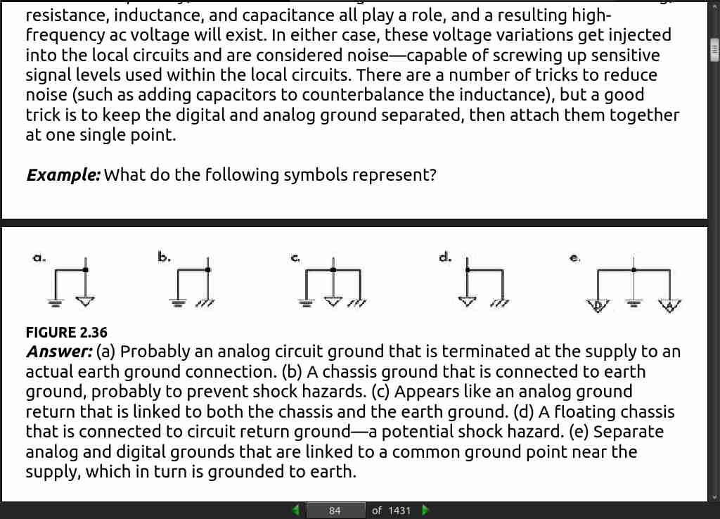
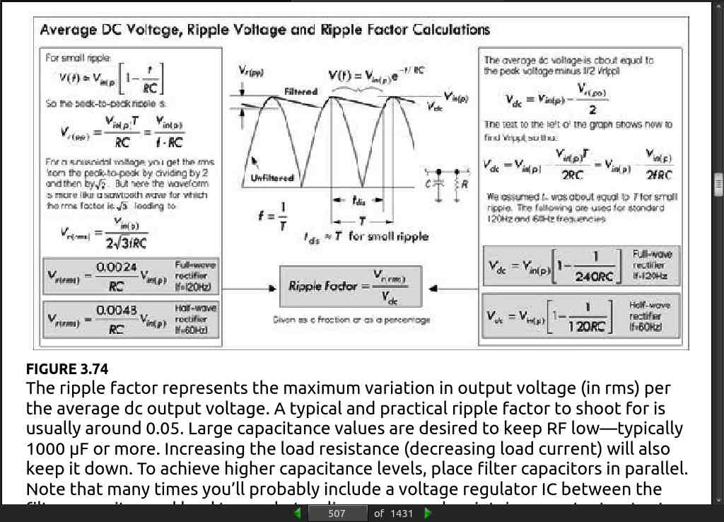
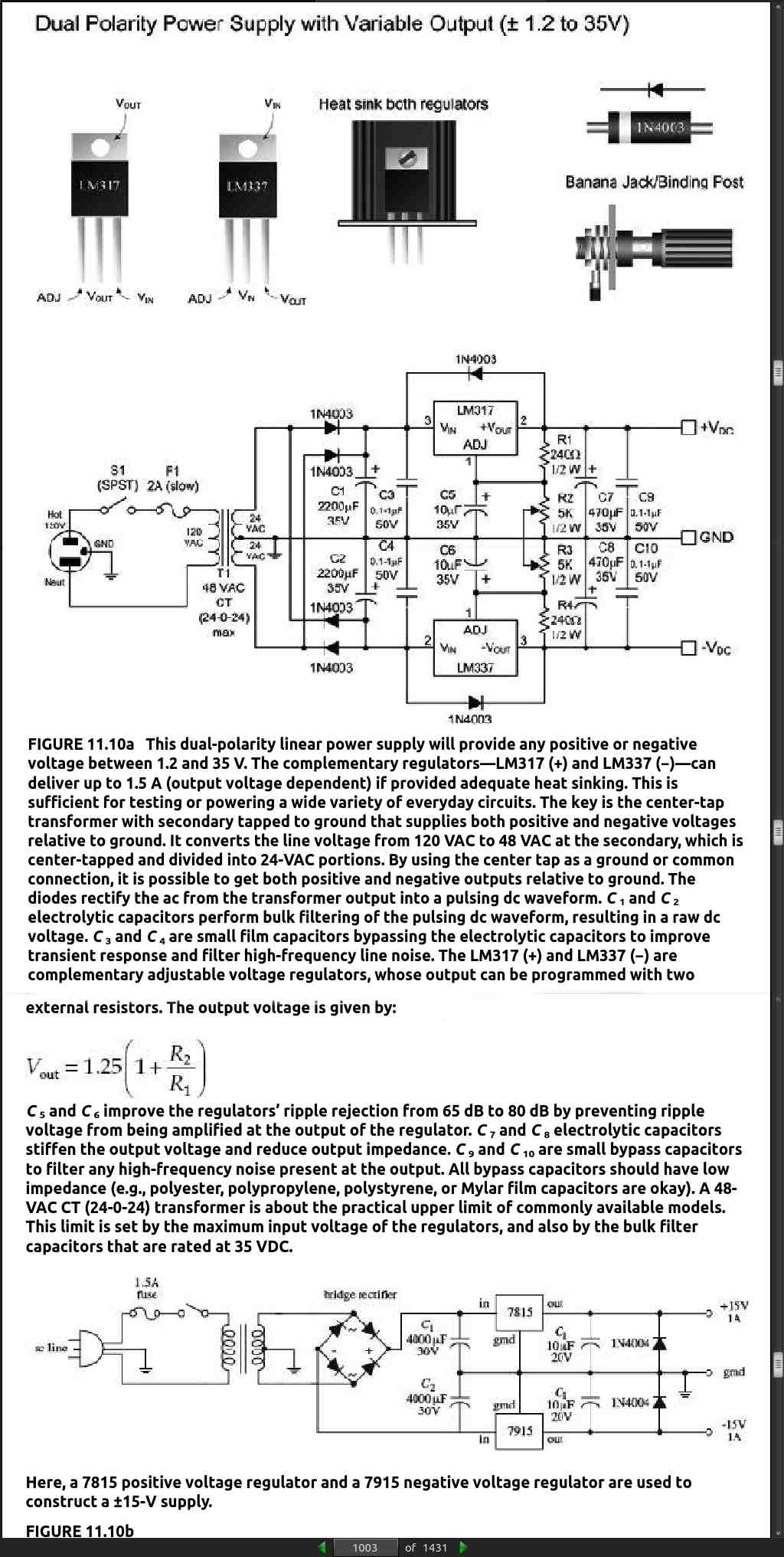
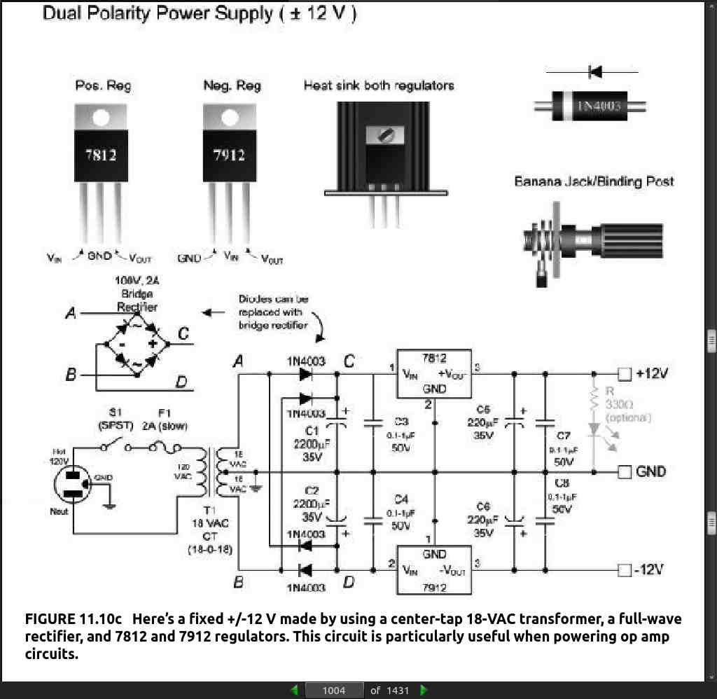
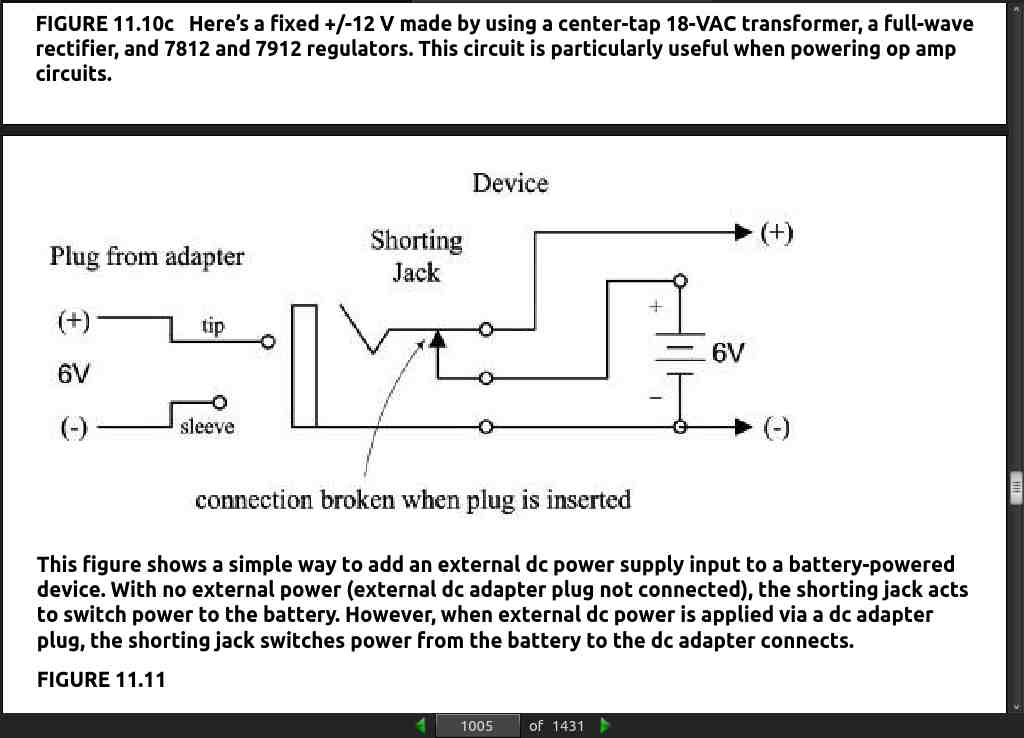
· CHAPTER 11: Voltage Regulators and Power Supplies
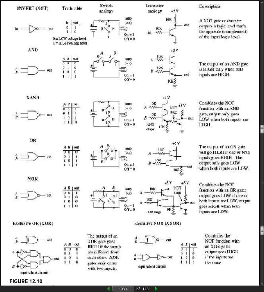
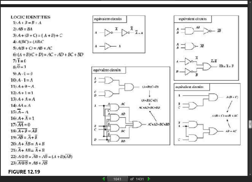
· CHAPTER 12: Digital Electronics
· CHAPTER 13: Microcontrollers
page 1219:
- Note: DSP is a complex area, and there are many good books devoted to this topic. Understanding Digital Signal Processing by Richard G. Lyons (Pearson,
- is one such book.
· CHAPTER 14: Motors
page 1280:
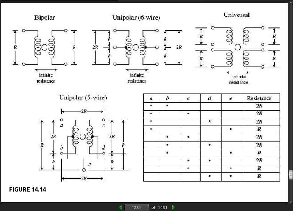
- When it comes to identifying the characteristics of an unknown stepper, the following suggestions should help. The vast majority of the steppers on the market today are unipolar, bipolar, or universal types. Based on this, you can guess that if your stepper has four leads, it is most likely a bipolar stepper. If the stepper has five leads, then the motor is most likely a unipolar with common center taps. If the stepper has six leads, it is probably a unipolar with separate center taps. A motor with eight leads would most likely be a universal stepper. (If you think your motor might be a variable-reluctance stepper, try spinning the shaft. If the shaft spins freely, the motor is most likely a variable-reluctance stepper. A coglike resistance indicates that the stepper is a permanent-magnet type.) Once you have determined what kind of stepper you have, the next step is to determine which leads are which. A simple way to figure this out is to test the resistance between various leads with an ohmmeter. Decoding the leads of a bipolar stepper is easy. Simply use an ohmmeter to determine which wire pair yields a low resistance value. A low resistance indicates that the two wires are ends of the same winding. If the two wires are not part of the same winding, the resistance will be infinite. A universal stepper can be decoded using a similar approach. Decoding a six-wire unipolar stepper requires isolating two three-wire pairs. From there, you figure out which wire is the common center tap by noticing which measured pair among the isolated three wires gives a unit R worth of resistance and which pair gives a unit of 2R worth of resistance (see Fig. 14.14). Now, decoding a five-wire unipolar (with common center tap) is a bit more tricky than the others because of the common, but hidden, center tap. To help decode this stepper, you can use the diagram and table shown in Fig. 14.14. (The dots within the table represent where the ohmmeter’s two probes are placed within the diagram.) With the table you isolate e (common tap wire) by noting when the ohmmeter gives a resistance of R units. Next, you determine which of the two wires in your hand is actually e by testing one of the two with the rest of the wires. If you always get R, then you are holding e, but if you get 2R, you are not holding e. Once the e wire is determined, any more ohmmeter deducing does not work—at least in theory—because you will always get 2R. The best bet now is to connect the motor to the driver circuitry and see if the stepper steps. If it does not step, fiddle around with the wires until it does.